Intermatic T104 Handleiding
Bekijk gratis de handleiding van Intermatic T104 (2 pagina’s), behorend tot de categorie Niet gecategoriseerd. Deze gids werd als nuttig beoordeeld door 66 mensen en kreeg gemiddeld 4.6 sterren uit 8 reviews. Heb je een vraag over Intermatic T104 of wil je andere gebruikers van dit product iets vragen? Stel een vraag
Pagina 1/2
BY THE MAKERS OF TIME CONTROLS
•HAS EXTERNAL
MANUAL OVERRIDE
SWITCH
•EASY TO INSTALL
•MATCH WATER HEATER
OFF TIMES TO PEAK
ENERGY PERIODS OF
YOUR UTILITY TO
REDUCE THEIR
DEMAND
STEP 1
A. CHECKING:
qMake sure the Time Switch and the water heater
VOLTAGES are the same.
qMake sure your water heater heater rating in WATTS
is not over the maximum capacity of this Time Switch.
qMake sure your water heater is wired with COPPER wire.
Do not connect ALUMINUM wires to the terminals of
this Time Switch. You may wish to consult an electrician
if your existing wires are ALUMINUM.
CAUTION - Disconnect electricity before you attempt to
remove or expose any wiring.
The
“LITTLE
GRAY
BOX”®
ELECTRIC
WATER HEATER
TIME SWITCH
Shown With
External Manual Lever
l) is too short. Allow for slack and 6 inches of hook-up
leads at each end to facilitate wiring connections.
C. MATERIALS YOU NEED
If your water heater is HARD WIRED: (See Fig. 2.)
1. Obtain a piece of cable, the SAME TYPE (that is,
metallic or plastic) and SAME GAUGE with COPPER
conductors to make Item n connection (and Item l, if
needed) as shown. See also gauge selection chart
below.
2. Obtain 2 cable connectors (Item o) to fit the cable
above.
If your water heater is CORD and PLUG connected:
(See Fig. 3)
1. Obtain the SAME TYPE and GAUGE cordset with plug
as presently used on (Item l) and 2 strain relief
grommets (Item p) to fit THIS cordset.
D. TOOL YOU NEED:
1/4 wide Screw Driver, Hammer, Drill, Pliers, Wire
Cutter and Stripper.
SIZE OF FUSE OR MINIMUM GAUGE 125 OR WATER HEATER CAPACITY
CIRCUIT BREAKER OF COPPER WIRE 250 V 125 VOLT 250 VOLT
AMP. AWG. AMP. WATTS WATTS
15 14 15 1875 3750
20 12 20 2500 5000
30 10 30 3750 7500
40 8 40 5000 10000
STEP 2
Disconnect electricity to water heater. Pull plug,
if cord connected; remove fuse or open circuit breaker
if hard wired. CAUTION: - You may have to
remove TWO fuses or switch TWO circuit breakers to the
OFF position. If you are not sure which circuit(s)
are for the water heater; use a tester or consult an
electrician.
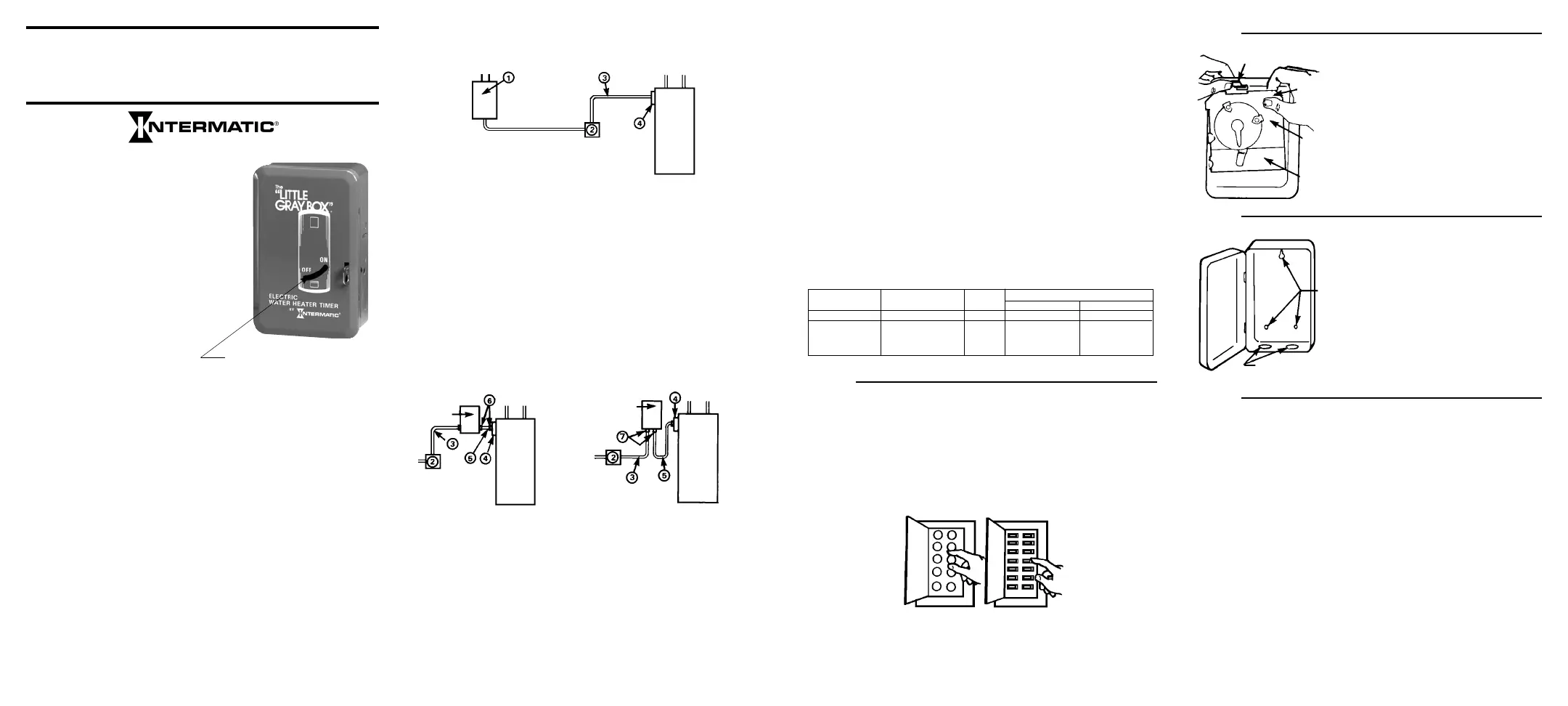
B. PLANNING AND MEASURING:
Here is how your water heater is wired now, BEFORE
the installation of this Time Switch:
jSERVICE BOX - Your water heater should have its own
(separate) fuse or circuit breaker in the electrical panel.
kJUNCTION BOX - You may or may not have this
convenience box. It may contain a disconnect switch
and/or receptacle if water heater is cord connected.
lWATER HEATER CONNECTION - This is a rigid or
flexible (metallic or plastic) cable containing 2, 3, or 4
insulated wires of different colors.
mWATER HEATER TERMINAL BOX - This is part of the
water heater where the power supply wires are connected
Here is your modified wiring, AFTER the Time Switch
is installed:
•Plan a convenient location for the Time Switch, preferably
eye level (also out of reach of small children), and such
that existing cable (Fig. 2 or Fig. 3, Item l) may be utilized.
•Measure the distance n from the Time Switch to Water
Heater Terminal Box m. Also measure distance l
from Time Switch to Junction Box if existing cable (Fig 2, Item
158--02141
Service
Box
Water
Heater
Water
Heater
Time
Switch
Time
Switch
Water
Heater
STEP 3
STEP 4
STEP 5
If your water heater is HARD WIRED:
Remove the cover of water heater terminal box (Fig. 1, Item
m) IS ELECTRICITY TURNED OFF?
NOTE COLORS OF WIRES. Disconnect wires and
cable connector. Remove the most convenient knockout of
the time switch case and attach cable (Fig. 2, Iteml) and
cable connector to case. Prepare another cable (Fig. 2,
Itemn) by stripping the ends of wires about half inch. Using
cable connector (Fig. 2, Item o), attach this cable to water
heater terminal box and then the wires to water heater
terminals.
NOTE: If you had green and / or white wires in the
terminal box before, you must connect the same
colors to these same terminals. TIGHTEN TERMINAL
SCREWS FIRMLY. Remove another knockout of the time
switch case and connect the other end of this cable to the
case, using the other cable connector, Item o.
Remove time switch
mechanism from case
by depressing the
spring holder at top
left above the time
switch mechanism, tilt
the mechanism for-
ward, and lift up and
out to remove from
case.
Mount time switch
case on wall as out-
lined in STEP 1B.
Mark mounting posi-
tion, drill holes into
mounting surface
and drive screws into
holes. Use anchors, if
necessary.
Spring
Holder
To Remove,
Tilt Top
Forward
And Lift Up.
Time
Switch
Mechanism
Plastic
Insulator
Mounting
Holes
Knockouts
2
3
4
Figure 1
Figure 2
Figure 3
HARD-WIREDCORD AND PLUG CONNECTED
Product specificaties
| Merk: | Intermatic |
| Categorie: | Niet gecategoriseerd |
| Model: | T104 |
Heb je hulp nodig?
Als je hulp nodig hebt met Intermatic T104 stel dan hieronder een vraag en andere gebruikers zullen je antwoorden
Handleiding Niet gecategoriseerd Intermatic

8 Juni 2026
8 Juni 2026
8 Juni 2026
19 April 2026
18 April 2026
18 April 2026
17 April 2026
16 April 2026
16 April 2026
16 April 2026
Handleiding Niet gecategoriseerd
Nieuwste handleidingen voor Niet gecategoriseerd
8 Juni 2026
8 Juni 2026
8 Juni 2026
8 Juni 2026
8 Juni 2026
8 Juni 2026
8 Juni 2026
8 Juni 2026
8 Juni 2026
8 Juni 2026