IMIT Chronomix-S 578180 Handleiding
IMIT
Thermostaat
Chronomix-S 578180
Bekijk gratis de handleiding van IMIT Chronomix-S 578180 (4 pagina’s), behorend tot de categorie Thermostaat. Deze gids werd als nuttig beoordeeld door 22 mensen en kreeg gemiddeld 4.7 sterren uit 11.5 reviews. Heb je een vraag over IMIT Chronomix-S 578180 of wil je andere gebruikers van dit product iets vragen? Stel een vraag
Pagina 1/4

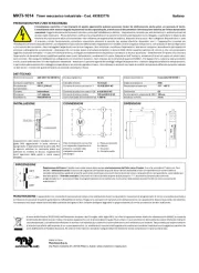
DESCRIZIONE PRODOTTO E SPECIFICHE TECNICHE PRODUCT DESCRIPTION AND TECHNICAL SPECIFICATIONS
INSTALLAZIONE E COLLEGAMENTI
DESCRIZIONE COMANDI E FUNZIONAMENTO
IT
ATTENZIONE! Si raccomanda di eseguire l’installazione del dispositivo rispettando
scrupolosamente le norme di sicurezza e le disposizioni di legge vigenti. Prima di effettuare
qualsiasi collegamento, accertarsi che l’interruttore generale sia stato disattivato.
Questo dispositivo è un cronotermostato con controllo elettronico della temperatura ed orologio
elettromeccanico giornaliero. Realizzato in conformità con le direttive CE applicabili, secondo le norme
EN 60730-2-9, EN 60730-2-7, è interamente fabbricato in Italia.
Alimentazione: Batterie Alcaline 2x1,5V LR6 (Tipo AA)
Durata batterie: > 1 anno
Portata massima contatti: 5A(1A) 250VAC
Tipo di azione: 1B
Classe ErP I (+1%) - 811/2013 (regolazione ON/OFF)
Classe ErP IV (+2%) - 811/2013 (regolazione TPI)
Temperatura ambiente: 0°C ÷ 50°C
Campo di regolazione temperatura COMFORT: 10°C÷30°C
Campo di regolazione temperatura RIDOTTA: 10°C÷26°C
Differenziale temperatura (regolazione ON/OFF): 0,5K
Installare il dispositivo lontano da fonti di calore e correnti d’aria, a circa 1,5m dal pavimento.
Aprire il dispositivo agendo con un cacciavite sui ganci laterali a sinistra quindi rimuovere il frontale
separandolo dalla base (Fig.2).
Rimuovere la vite e sganciare il coprimorsetto (Fig.3 A).
Infilare i cavi attraverso l’apertura sul fondo (Fig.3 C).
Fissare la base alla parete o sulla scatola incasso con delle viti, utilizzando gli appositi fori (Fig.3 B).
Per agevolare i collegamenti elettrici, estrarre la morsettiera a 3 vie (Fig.3 D), facendo una piccola
pressione verso l’esterno sulla levetta che tiene fissata la morsettiera alla base (Fig.3 E).
Collegare i cavi alla morsettiera come indicato (Fig.4).
Dopo avere collegato i cavi, inserire la morsettiera nella propria sede premendola delicatamente fino allo
scatto della levetta.
Riposizionare il coprimorsetto riavvitandolo alla base (Fig.3 A).
Selezionare la modalità di regolazione della temperatura, come descritto al capitolo “TIPO DI REGOLAZIONE”.
Inserire le batterie nell’apposita sede all’interno del frontale rispettando la polarità (Fig.5).
Rimettere il frontale sulla base, inclinandolo a 45° ed agganciare i dentelli (Fig.6).
Richiudere il dispositivo, allineando i contatti con la morsettiera sulla base, finché la parte superiore
tocca i ganci di blocco (Fig.7 A).
Premere leggermente per agevolare l’incastro delle due parti.
SOSTITUZIONE BATTERIE
Sostituire le batterie quando la spia rossa lampeggia (Fig.1 G). Aprire il dispositivo agendo con un
cacciavite sui ganci laterali a sinistra quindi rimuovere il frontale separandolo dalla base (Fig.2) e
sostituire le batterie come indicato (Fig.5).
Richiudere il dispositivo come indicato nelle istruzioni di installazione.
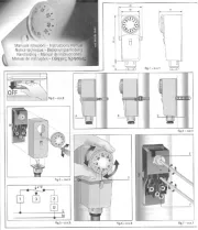
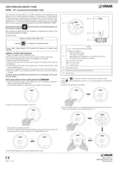
LEGENDA COMANDI (Fig.1)
A = Manopola impostazione temperatura ridotta
B = Manopola impostazione temperatura comfort
C = Selettore modo funzionamento
D = Indice orario ►
E = Orologio programmatore
F = Posizione selettori per temperatura Comfort/Ridotta
G = Spia di segnalazione batterie scariche ed allarmi
REGOLAZIONE OROLOGIO
Ruotare il disco dell’orologio in senso orario posizionando l’indicatore sull’ora attuale (Fig.1 D).►
Ricordare di reimpostare l’orologio passando da ora legale ad ora solare e viceversa.
MODO OFF
Posizionare il selettore (Fig.1 C) su per spegnere il termostato.
In caso di temperatura ambiente < 5°C si attiva la funzione antigelo.
FUNZIONAMENTO MANUALE
Posizionare il selettore (Fig.1 C) sul simbolo .
La manopola temperatura ridotta (Fig.1 A) e l’orologio (Fig.1 E) sono disabilitati.
Impostare la temperatura desiderata: posizionare il valore desiderato sotto l’indicatore di riferimento
ruotando la manopola Comfort (Fig.1 B).
FUNZIONAMENTO AUTOMATICO
La temperatura regolata nell’ambiente (impostata con le manopole Comfort o Ridotta) dipende dalle
impostazioni effettuate sull’orologio e cambia automaticamente.
Posizionare il selettore (Fig.1 C) sul simbolo .
Impostare la temperatura comfort: posizionare il valore desiderato sotto l’indicatore di riferimento
ruotando la manopola Comfort (Fig.1 B).
Impostare la temperatura ridotta: posizionare il valore desiderato sotto l’indicatore di riferimento
ruotando la manopola temperatura ridotta (Fig.1 A).
Programmare l’orologio posizionando le levette (Fig.1 F):
• verso l’esterno per avere la temperatura comfort ;
• verso il centro per avere la temperatura ridotta .
Verificare che l’indice dell’orologio indichi l’ora attuale ed eventualmente agire come indicato al capitolo
“REGOLAZIONE OROLOGIO”.
TIPO DI REGOLAZIONE (Riservato agli installatori)
La posizione dei ponticelli A e B (Fig.8), permette al dispositivo di funzionare con due differenti tipi di
regolazione:
• ON / OFF (impostazione di fabbrica): Il dispositivo si attiva con temperatura ambiente inferiore alla
temperatura impostata e si spegne quando la raggiunge.
A=Presente, B= Presente
• TPI: Il dispositivo si attiva con temperatura ambiente inferiore a quella impostata e, avvicinandosi
alla temperature richiesta, riduce i periodi di funzionamento della caldaia ottimizzando il comfort
ambientale e riducendo sensibilmente i consumi.
A=Assente, B=Presente (ottimizzato per impianti a radiatori)
A=Assente, B=Assente (ottimizzato per impianti a pavimento)
IMPORTANTE: il riposisizionamento dei ponticelli deve essere eseguito prima di inserire le batterie o
comunque con il dispositivo privo di batterie.
SEGNALAZIONE ANOMALIE
La spia rossa del dispositivo (Fig.1 G) si attiva per segnalare:
• con 2 lampeggi lenti: batterie quasi scariche. Sostituirle al più presto.
• con 2 lampeggi veloci: batterie esaurite. Sostituirle per ripristinare il funzionamento del dispositivo.
• con lampeggio veloce continuo: anomalia interna del dispositivo. Sostituire le batterie e verificare le
condizioni ambientali di funzionamento prima di sostituire il dispositivo.
This device is a chronothermostat with electronic temperature control and daily electromechanical clock.
Produced in accordance with the applicable EC directives, according to the standards EN 60730-2-9,
EN 60730-2-7, it is entirely manufactured in Italy.
Power supply: 2x1.5V LR6 Alkaline Batteries (Type AA)
Battery life: > 1 year
Maximum contact capacity: 5A(1A) 250VAC
Action type: 1B
ErP class I (+1%) - 811/2013 (ON/OFF regulation)
ErP class IV (+2%) - 811/2013 (TPI regulation)
Operating Temperature: 0°C ÷ 50°C
COMFORT temperature regulation range: 10°C÷30°C
REDUCED temperature regulation range: 10°C÷26°C
Temperature differential (ON/OFF regulation): 0.5K
Install the device away from heat sources and and drafts, about 1.5m from the floor.
Using a screwdriver open the device via the side hooks on the left and then remove the front, separating
it from the base (Fig.2).
Remove the screw and detach the terminal cover (Fig.3 A).
Insert the cables through the opening on the bottom (Fig.3 C).
Attach the base to the wall or on the flush mounted box with screws, using the relevant holes (Fig.3 B).
To facilitate the electrical connections, remove the 3-way terminal block (Fig.3 D), exerting slight
outward pressure on the lever that secures the terminal block to the base (Fig.3 E).
Connect the wires to the terminal block as indicated (Fig.4).
After connecting the cables, insert the terminal block into place, pressing it gently until the lever clicks.
Replace the terminal cover, screwing it back onto the base (Fig.3 A).
Select the temperature regulation mode, as described in the chapter “REGULATION TYPE”.
Insert the batteries into the slot inside the front ensuring correct polarity (Fig.5).
Refit the front onto the base, tilting it 45° and engage the notches (Fig.6).
Close the device again, aligning the contacts with the terminal block on the base until the upper part
touches the lock hooks (Fig.7 A) .
Press lightly to facilitate connection of the two parts.
BATTERY REPLACEMENT
Replace the batteries when the red light flashes (Fig.1 G) . Using a screwdriver open the device via the
side hooks on the left and then remove the front, separating it from the base (Fig.2) and replace the
batteries as indicated (Fig.5).
Close the device again as shown in the installation instructions.
COMMANDS LEGEND (Fig.1)
A = Reduced temperature setting knob
B = Comfort temperature setting knob
C = Operating mode selector
D = Timer index ►
E = Programmer clock
F = Position of selectors for Comfort/Reduced temperature
G = Light for low battery warning and alarms
CLOCK ADJUSTMENT
Rotate the disc of the clock clockwise positioning the indicator on the current time (Fig.1 D).►
Remember to reset the clock moving from Daylight Saving Time to Standard Time and vice versa.
OFF MODE
Position the selector (Fig.1 C) on to turn off the thermostat.
In case of ambient temperature < 5°C the anti-freeze function is activated.
MANUAL OPERATION
Position the selector (Fig.1 C) on the symbol .
The reduced temperature knob (Fig.1 A) and the clock (Fig.1 E) are disabled.
Set the desired temperature: position the desired value under the reference indicator by turning the
Comfort knob (Fig.1 B).
AUTOMATIC OPERATION
The temperature regulated in the environment (set with the Comfort or Reduced knobs) depends on the
settings chosen on the clock and changes automatically.
Position the selector (Fig.1 C) on the symbol .
Set the comfort temperature: position the desired value under the reference indicator by turning the
Comfort knob (Fig.1 B).
Set the reduced temperature: position the desired value under the reference indicator by turning the
reduced temperature knob (Fig.1 A).
Program the clock by positioning the levers (Fig.1 F):
• outwards for the comfort temperature ;
• towards the centre for reduced temperature .
Check that the index of the clock shows the current time and if necessary proceed as indicated in chapter
“CLOCK ADJUSTMENT”.
REGULATION TYPE (Reserved for installers)
The position of the jumpers A and B (Fig.8) allows the device to work with two different types of
temperature regulation:
• ON / OFF (factory setting): The device is activated when the ambient temperature is lower than the
temperature set and turns off when it reaches the temperature set.
A=Present, B= Present
• TPI: The device is activated when the ambient temperature is lower than the temperature set and,
approaching the required temperature, reduces the operating periods of the boiler, optimising
environmental comfort and reducing energy consumption.
A=Absent, B=Present (optimised for radiator systems)
A=Absent, B=Absent (optimised for floor systems)
IMPORTANT: repositioning of the jumpers must be performed before inserting the batteries or in any
case with the device with batteries removed.
FAULT INDICATION
The red light of the device (Fig.1 G) is activated to indicate:
• with 2 slow flashes: batteries almost flat. Replace them as soon as possible.
• with 2 quick flashes: batteries flat. Replace them to restore functioning of the device.
• with continuous quick flashing: fault inside the device. Replace the batteries and check the operating
environment conditions before replacing the device.
Intervallo minimo impostabile: 15 minuti
Sonda di temperatura: NTC 100KΩ@25°C
Grado di protezione: IP20
Classe di isolamento: Tipo II (doppio isolamento)
Grado d’inquinamento: 2
Software: classe A
Resistenza al calore ed al fuoco: Categoria D
Temperatura di stoccaggio: -25÷60°C
Tensione nominale di tenuta ad impulso: 2,5kV
Montaggio: a parete
Minimum settable interval : 15 minutes
Temperature sensor: NTC 100K @25°CΩ
Degree of protection: IP20
Insulation class: Type II (double insulation)
Pollution degree: 2
Software: class A
Resistance to heat and fire: Category D
Storage temperature: -25÷60°C
Rated impulse withstand voltage: 2.5kV
Mounting: wall
WARNING! It is recommended to install the device in strict accordance with the safety
regulations and laws in force. Before making any connection, make sure that the main
switch is off.
INSTALLATION AND CONNECTIONS
DESCRIPTION OF COMMANDS AND OPERATION
EN
Fig. 1
16
18
20
22
24
18
16
18
20
22
24
1
8
A
B
C
D
E
F
G
A
DE
A
B
C
Fig. 2 Fig. 3
Fig. 4
A
B
Fig. 5 Fig. 6
Fig. 7 Fig. 8
A
B
IMIT CONTROL SYSTEM s.r.l.
Via Varallo Pombia,19 - Castelletto Sopra Ticino (NO)
Tel (+39)0331941600 - Fax (+39)0331973100
www.imit.it - info@controlsys.it
Cronotermostato elettronico giornaliero
Daily electronic chronothermostat
Chronothermostat electronique journalier
Cronotermostato electronico diario
16
18
20
22
24
1
8
077619 Rev0217
CHRONOMIX-S
Manuale_Chronomix-S_multilingue_390x400.indd 1 03/02/17 14:16


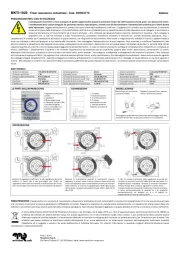
DESCRIPTION DU PRODUIT ET SPÉCIFICATIONS TECHNIQUES
Ce dispositif est un thermostat programmable avec contrôle électronique de la température et une
horloge électromécanique quotidienne. Réalisé conformément aux directives CE applicables, selon les
normes EN 60730-2-9, EN 60730-2-7, il est entièrement fabriqué en Italie.
Alimentation : Piles Alcalines 2x1,5V LR6 (Type AA)
Durée des piles: > 1 an
Intensité maximale des contacts : 5A(1A) 250VAC
Types d’action : 1B
Classe ErP I (+1%) - 811/2013 (réglage ON/OFF)
Classe ErP IV (+2%) - 811/2013 (réglage TPI)
Température ambiante : 0°C ÷ 50°C
Champ de réglage de la température CONFORT : 10°C ÷ 30°C
Champ de réglage de la température RÉDUITE : 10°C ÷ 26°C
Ecart de températur (réglage ON/OFF) : 0,5K
Installer le dispositif loin des sources de chaleur et des courants d’air, à environ 1,5 m du sol.
Ouvrir le dispositif en faisant levier avec un tournevis sur les crochets latéraux à gauche, puis enlever la
façade en la séparant de la base (Fig.2).
Enlever les vis et détacher le couvre-bornes (Fig.3 A).
Enfiler les câbles au travers de l’ouverture du fond (Fig.3 C).
Fixer la base au mur ou sur le boîtier encastré avec les vis, en utilisant les trous prévus à cet effet (Fig.3 B).
Pour faciliter les branchements électriques, extraire la plaque à bornes à 3 voies (Fig.3 D), en exerçant
une légère pression vers l’extérieur sur la patte qui maintient la plaque à bornes fixée à la base (Fig.3 E) .
Brancher les fils à la plaque à bornes comme indiqué (Fig.4).
Après avoir branché les fils, introduire la plaque à bornes dans son logement en l’enfonçant délicatement
jusqu’à ce qu’au déclic de la patte.
Remettre le couvre-bornes en le revissant à la base (Fig.3 A).
Sélectionner la modalité de réglage de la température, comme décrit au chapitre “TYPE DE RÉGLAGE”.
Introduire les piles dans l’emplacement prévu à cet effet à l’intérieur de la façade en respectant la
polarité (Fig.5).
Remettre la façade sur la base, en l’inclinant à 45° et l’accrocher aux encoches (Fig.6).
Refermer le dispositif, en alignant les contacts avec la plaque à bornes sur la base, jusqu’à ce que la partie
supérieure touche les crochets de blocage (Fig.7 A).
Appuyer légèrement pour aider les deux parties à s’emboîter.
REMPLACEMENT DES BATTERIES
Remplacer les batteries quand le voyant rouge clignote (Fig.1 G). Ouvrir le dispositif en faisant levier
avec un tournevis sur les crochets latéraux à gauche, puis enlever la façade en la séparant de la base
(Fig.2) et remplacer les batteries comme indiqué (Fig.5).
Refermer le dispositif comme indiqué dans la notice d’installation.
LÉGENDE COMMANDES (Fig.1)
A = Molette configuration température réduite
B = Molette configuration température confort
C = Sélecteur mode de fonctionnement
D = Index horaire ►
E = Horloge programmateur
F = Position des sélecteurs pour température Confort/Réduite
G = Voyant pour batteries épuisées et alarmes
RÉGLAGE DE L’HORLOGE
Tourner le disque de l’horloge dans le sens des aiguilles d’une montre en plaçant l’indicateur sur ►
l’heure actuelle (Fig.1 D).
Ne pas oublier de re-configurer l’horloge lors des changements saisonniers de l’heure.
MODE OFF
Mettre le sélecteur (Fig.1 C) sur pour éteindre le thermostat.
Si la température ambiante est < à 5°C la fonction hors gel s’active.
FONCTIONNEMENT MANUEL
Mettre le sélecteur (Fig.1 C) sur le symbole .
La molette température réduite (Fig.1 A) et l’horloge (Fig.1 E) sont désactivées.
Régler la température souhaitée : placer la valeur souhaitée sous l’indicateur de référence en tournant
la molette Confort (Fig.1 B).
FONCTIONNEMENT AUTOMATIQUE
La température ambiante réglée (configurée avec les molettes Confort ou Réduite) dépend des paramètres
configurés sur l’horloge et change automatiquement.
Mettre le sélecteur (Fig.1 C) sur le symbole .
Régler la température confort : placer la valeur souhaitée sous l’indicateur de référence en tournant la
molette Confort (Fig.1 B).
Régler la température réduite : placer la valeur souhaitée sous l’indicateur de référence en tournant la
molette réduite (Fig.1 A).
Programmer l’horloge en mettant les leviers (Fig.1 F):
• vers l’extérieur pour avoir la température confort ;
• vers le centre pour avoir la température réduite .
Vérifier que l’index de l’horloge indique l’heure actuelle et, si nécessaire, agir comme indiqué au chapitre
“RÉGLAGE DE L’HORLOGE”.
TYPE DE RÉGLAGE (Réservé aux installateurs)
La position des ponts A et B (Fig.8), permet au dispositif de fonctionner avec deux types de réglages
différents :
• ON / OFF (Configuration d’usine) : Le dispositif s’active lorsque la température ambiante est
inférieure à la température configurée et il s’éteint quand il a atteint.
A=Présent, B= Présent
• TPI : Le dispositif s’active quand la température ambiante est inférieure à la température configurée
puis, quand il s’approche de la température demandée, il réduit les périodes de fonctionnement de la
chaudière en optimisant le confort et en réduisant sensiblement les coûts.
A=Absent, B=Présent (optimisé pour les installations à radiateurs)
A=Absent, B=Absent (optimisé pour les installations au sol)
IMPORTANT : le replacement des ponts doit être effectué avant d’introduire les batteries et, dans tous
les cas, sans les piles dans le dispositif.
SIGNALEMENT DES ANOMALIES
Le voyant rouge du dispositif (Fig.1 G) s’active pour signaler :
• 2 clignotements lents : batteries presque épuisées. Les remplacer dès que possibles.
• 2 clignotements rapides : batteries épuisées. Les remplacer pour rétablir le fonctionnement du dispositif.
• clignotement rapide et continu : anomalie du dispositif. Remplacer les batteries et contrôler les
conditions environnementales de fonctionnement avant de remplacer le dispositif.
ATTENTION ! Nous recommandons d’effectuer l’installation du dispositif en respectant
scrupuleusement les normes de sécurité et les dispositions de loi en vigueur. Avant
d’effectuer tout branchement, vérifier que l’interrupteur général est désactivé.
INSTALLATION ET BRANCHEMENTS
DESCRIPTION DES COMMANDES ET FONCTIONNEMENT
DESCRIPCIÓN DEL PRODUCTO Y ESPECIFICACIONES TÉCNICAS
Este dispositivo es un cronotermostato con control electrónico de la temperatura y reloj electromecánico
diario. Realizado cumpliendo con los requisitos de las directivas CE aplicables, en conformidad con las
normas EN 60730-2-9, EN 60730-2-7, está totalmente fabricado en Italia.
Alimentación: Baterías Alcalinas 2x1,5V LR6 (Tipo AA)
Duración baterías: > 1 año
Capacidad máxima contactos: 5A(1A) 250VAC
Tipo de acción: 1B
Clase ErP I (+1%) - 811/2013 (regulación ON/OFF)
Clase ErP IV (+2%) - 811/2013 (regulación TPI)
Temperatura ambiente: 0°C ÷ 50°C
Campo de regulación temperatura CONFORT: 10°C÷30°C
Campo de regulación temperatura REDUCIDA: 10°C÷26°C
Diferencial temperatura (regulación ON/OFF): 0,5K
Instalar el dispositivo lejos de fuentes de calor y corrientes de aire, aproximadamente a 1,5m del suelo.
Abrir el dispositivo actuando con un destornillador en los ganchos laterales de la izquierda luego quitar
el frente separándolo de la base (Fig.2).
Quitar el tornillo y desenganchar el cubre abrazadera (Fig.3 A).
Colocar los cables a través de la abertura del fondo (Fig.3 C).
Fijar la base en la pared o en la caja empotrada con tornillos, utilizando los agujeros específicos (Fig.3 B).
Para facilitar las conexiones eléctricas, extraer la terminal de conexión de 3 vías (Fig.3 D), ejerciendo
una pequeña presión hacia el exterior en la palanca que mantiene fijada la terminal de conexión a la
base (Fig.3 E).
Conectar los cables a la terminal de conexión como se indica (Fig.4).
Después de haber conectado los cables, insertar el terminal de conexión en su compartimiento
presionándolo con cuidado hasta el clic de la palanca.
Volver a colocar el cubre abrazadera atornillándolo en la base (Fig.3 A).
Seleccionar la modalidad de regulación de la temperatura, como se describe en el capítulo
“TIPO DE REGULACIÓN”.
Colocar las baterías en el adecuado compartimiento en el interior del frente respetando la polaridad (Fig.5).
Volver a colocar el frente en la base, inclinándola a 45° y enganchar los dentículos (Fig.6).
Cerrar el dispositivo, alineando los contactos con la terminal de conexión en la base, hasta que la parte
superior toque los ganchos de bloqueo (Fig.7 A).
Presionar levemente para facilitar el encastre de las dos partes.
CAMBIO DE LAS BATERÍAS
Sustituir las baterías cuando el indicador luminoso rojo parpadea (Fig.1 G). Abrir el dispositivo actuando
con un destornillador en los ganchos laterales de la izquierda luego quitar el frente separándolo de la
base (Fig.2) y cambiar las baterías como se indica (Fig.5).
Cerrar el dispositivo como se indica en las instrucciones de instalación.
NOTA MANDOS (Fig.1)
A = Botón configuración temperatura reducida
B = Botón configuración temperatura confort
C = Selector modo funcionamiento
D = Índice horario ►
E = Reloj programador
F = Posición selectores para temperatura Confort/Reducida
G = Indicador luminoso de señalización baterías descargadas y alarmas
REGULACIÓN RELOJ
Girar el disco del reloj en sentido horario colocando el indicador en la hora actual (Fig.1 D).►
Recordar volver a configurar el reloj pasando de la hora legal a la hora solar y viceversa.
MODO OFF
Colocar el selector (Fig.1 C) en para apagar el termostato.
En caso de temperatura ambiente < 5°C se activa la función antihielo.
FUNCIONAMIENTO MANUAL
Colocar el selector (Fig.1 C) en el símbolo .
El botón temperatura reducida (Fig.1 A) y el reloj (Fig.1 E) están inhabilitados.
Configurar la temperatura deseada: colocar el valor deseado debajo el indicador de referencia girando el
botón Confort (Fig.1 B).
FUNCIONAMIENTO AUTOMÁTICO
La temperatura regulada en el ambiente (configurada con los botones Confort o Reducida) depende de
las configuraciones realizadas en el reloj y cambia automáticamente.
Colocar el selector (Fig.1 C) en el símbolo .
Configurar la temperatura confort: colocar el valor deseado debajo el indicador de referencia girando el
botón Confort (Fig.1 B).
Configurar la temperatura reducida: colocar el valor deseado debajo el indicador de referencia girando el
botón temperatura reducida (Fig.1 A).
Programar el reloj colocando las perillas (Fig.1 F):
• hacia el exterior para tener la temperatura confort ;
• hacia el centro para tener la temperatura reducida .
Verificar que el índice del reloj indique la hora actual y eventualmente actuar como se indica en el
capítulo “REGULACIÓN RELOJ”.
TIPO DE REGULACIÓN (Reservado a los instaladores)
La posición de los puentes A y B (Fig.8), permite al dispositivo funcionar con dos diferentes tipos de
regulación:
• ON / OFF (configuración de fábrica) : El dispositivo se activa con temperatura ambiente inferior a la
temperatura configurada y se apaga cuando la alcanza.
A=Presente, B= Presente
• TPI : El dispositivo se activa con temperatura ambiente inferior a la configurada y, acercándose a la
temperatura solicitada, reduce los períodos de funcionamiento de la caldera optimizando el confort
ambiental y reduciendo sensiblemente los consumos.
A=Ausente, B=Presente (optimizado para instalaciones de radiadores)
A=Ausente, B=Ausente (optimizado para instalaciones de pavimento)
IMPORTANTE: la re colocación de los puentes se debe realizar antes de introducir las baterías o con el
dispositivo sin baterías.
SEÑALIZACIÓN ANOMALÍAS
El indicador luminoso rojo del dispositivo (Fig.1 G) se activa para señalizar :
• con 2 parpadeos lentos: baterías casi descargadas. Cambiarlas lo más pronto posible.
• con 2 parpadeos rápidos: baterías agotadas. Cambiarlas para restablecer el funcionamiento del
dispositivo.
• con parpadeo continuo : anomalía interna del dispositivo. Cambiar las baterías y controlar las
condiciones ambientales de funcionamiento antes de cambiar el dispositivo.
Intervalo mínimo configurable: 15 minutos
Sonda de temperatura: NTC 100KΩ@25°C
Grado de protección: IP20
Clase de aislamiento: Tipo II (doble aislamiento)
Grado de contaminación: 2
Software: clase A
Resistencia al calor y al fuego: Categoría D
Temperatura de almacenamiento: -25÷60°C
Tensión nominal soportable de impulso: 2,5kV
Montaje: a la pared
¡ATENCIÓN! Se recomienda realizar la instalación del dispositivo respetando rigurosamente
las normas de seguridad y las disposiciones de ley vigentes. Antes de realizar alguna
conexión, asegurarse que el interruptor general se haya desconectado.
INSTALACIÓN Y CONEXIONES
DESCRIPCIÓN MANDOS Y FUNCIONAMIENTO
Intervalle minimum paramétrable : 15 minutes
Sonde de température : NTC 100KΩ@25°C
Degré de protection : IP20
Classe d’isolation : Type II (double isolation)
Degré de pollution : 2
Logiciel : classe A
Résistance à la chaleur et au feu : Catégorie D
Température de stockage : -25÷60°C
Tension nominale de choc : 2,5kV
Montage : mural
FR ES
Fig. 1
16
18
20
22
24
18
16
18
20
22
24
1
8
A
B
C
D
E
F
G
A
DE
A
B
C
Fig. 2 Fig. 3
Fig. 4
A
B
Fig. 5 Fig. 6
Fig. 7 Fig. 8
A
B
IMIT CONTROL SYSTEM s.r.l.
Via Varallo Pombia,19 - Castelletto Sopra Ticino (NO)
Tel (+39)0331941600 - Fax (+39)0331973100
www.imit.it - info@controlsys.it
Cronotermostato elettronico giornaliero
Daily electronic chronothermostat
Chronothermostat electronique journalier
Cronotermostato electronico diario
16
18
20
22
24
1
8
077619 Rev0217
CHRONOMIX-S
Manuale_Chronomix-S_multilingue_390x400.indd 2 03/02/17 14:16
Product specificaties
| Merk: | IMIT |
| Categorie: | Thermostaat |
| Model: | Chronomix-S 578180 |
Heb je hulp nodig?
Als je hulp nodig hebt met IMIT Chronomix-S 578180 stel dan hieronder een vraag en andere gebruikers zullen je antwoorden
Handleiding Thermostaat IMIT
19 November 2024

23 Oktober 2023

23 Oktober 2023

23 Oktober 2023

23 Oktober 2023

23 Oktober 2023

23 Oktober 2023

23 Oktober 2023

23 Oktober 2023

23 Oktober 2023
Handleiding Thermostaat
- EVE
- Qubino
- Gewiss
- Essent
- Sygonix
- Somfy
- Sinustec
- Energenie
- Radson
- Warmup
- VDH
- Kemot
- Weishaupt
- Ferguson
- Feller
Nieuwste handleidingen voor Thermostaat
2 September 2025
1 September 2025
30 Augustus 2025
30 Augustus 2025
26 Augustus 2025
26 Augustus 2025
26 Augustus 2025
26 Augustus 2025
26 Augustus 2025
26 Augustus 2025