Extron OCS 100C Handleiding
Extron
Bewegingsdetector
OCS 100C
Bekijk gratis de handleiding van Extron OCS 100C (6 pagina’s), behorend tot de categorie Bewegingsdetector. Deze gids werd als nuttig beoordeeld door 62 mensen en kreeg gemiddeld 5.0 sterren uit 31.5 reviews. Heb je een vraag over Extron OCS 100C of wil je andere gebruikers van dit product iets vragen? Stel een vraag
Pagina 1/6

1
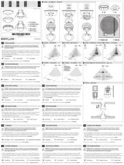
Occupancy Sensor OCS 100C • Setup Guide
The OCS 100C is a ceiling mounted occupancy sensor that incorporates ultrasonic (US) and passive infrared (PIR) into a dual
technology sensor. The US sensor emits ultrasonic sound waves into an area and measures the speed of their return to detect
the presence of people. Frequency changes are caused by the movement of people, which is detected by the US waves. The PIR
sensor detects the presence of people based on the difference between the heat generated by moving people versus the ambient
room temperature.
The OCS 100C has a 24 VDC power input, ground/common connection, normally open/closed relay, photocell, and occupancy
output connections.
Front Panel Features
Ultrasonic
Sensors
Green LED
(status indicator)
Green LED
(status indicator)
Retainer Ring
Infrared/Photocell
Lens
Figure 1. OCS 100C Front Panel Features
Control
Blue Photocell Dial
Red Infrar
ed
Sensitivity Dial
Black
Timer Dial
Green Ultrasonic
Range Dial
DIP Switches (B)
DIP Switches (A)
l
D
I
P
A)
1
A
2
3
4
ON ON
1
B
2
3
4
1234
1234
Figure 2. OCS 100C Controls
The settings for DIP Switches B3 (timer adjust) and B4
(sensitivity adjust) can be set to:
• Automatic mode — The sensors automatically adjust for
changes in usage and seasons, eliminating the need for
manual adjustments and improving system performance.
• Manual mode — The user sets the parameters of the
sensors using the following dials.
NOTE:
• The black timer dial is inactive when the B3 timer adjust DIP Switch is in Automatic mode.
• The red infrared sensitivity dial and green ultrasonic range dial are inactive when the B4 sensitivity adjust DIP Switch is
set to Automatic mode.
• Ultrasonic sensors (4) — Detect movement in the room, based
on ultrasonic sound waves.
• Green LED status indicators (2) — Flash when the ultrasonic
sensors detect occupancy.
• Infrared/Photocell lens — Diffracts the incoming light and
directs the light to the infrared/photocell sensor. The infrared/
photocell sensor, controls and DIP switches are located behind
the lens.
• Red LED status indicator — Located behind the
infrared lens, this LED ashes when the infrared sensor
detects occupancy.
• Retainer Ring — Holds the optional IR mask in place. Remove
to access all controls and DIP switches.
• DIP Switches A —
A OPERATION OFF ON
1Not used Not usedNot used*
2Threshold Auto threshold
adjustment*
High
sensitivity
(low turn on
threshold)
3LED indicators LEDs LEDs enabled*
disabled
4Automatic adjust reset Toggle to reset ( )Default: OFF
*Default
• DIP Switches B —
B OPERATION OFF ON
1Strong airow
compensator
Disabled* Enabled
2Over doorway mount EnabledDisabled*
3Timer adjust Automatic Manual*
4Sensitivity adjust Automatic Manual*
*Default

2
Occupancy Sensor OCS 100C • Setup Guide (Continued)
• Black Timer Dial (see on the previous page) — The occupancy sensor has a built in timer feature. When the sensor figure2
detects motion, it instantly triggers ON (high).
Once occupancy is no longer detected, the timer begins. If no motion is detected and the timer expires, then the sensor
triggers OFF (low).
Use the black timer dial to set the amount of time before the sensor triggers OFF.
NOTE: B3 DIP Switch must be set to ON for Manual mode, in order to adjust the timer manually.
• Ranges from 8 minutes to 42 minutes.
• Full counter clock wise (CCW) = 8 minutes
• Full clock wise (CW) = 42 minutes
• To enter the test mode (8 second timer) follow the steps below:
1. Open the retainer ring.
2. Rotate the black timer dial to about midway (12 o’clock).
3. Return to minimum setting (full CCW).
4. The timer will remain in the 8 second test mode for 1 hour, then automatically reset to 8 minutes.
5. To manually force the timer out of the 8 second test mode, turn the timer adjustment approximately 1/16 inch
clockwise. The setting is slightly above minimum (just above the 8 minute setting.
• Red Infrared Sensitivity Dial — Adjust this dial to increase or decrease infrared sensitivity.
• Turn clockwise (CW) to increase sensitivity.
• Turn counter clockwise (CCW) to decrease sensitivity.
• The factory default setting is at 75%.
• Green Ultrasonic Range Dial — Adjust this dial to increase or decrease ultrasonic sensitivity.
• Turn clockwise (CW) to increase sensitivity.
• Turn counter clockwise (CCW) to decrease sensitivity.
• The factory default setting is at 50%.
NOTE: B4 DIP Switch must be set to ON for Manual mode, in order to adjust the Red Infrared Sensitivity Dial Green or the
Ultrasonic Range Dial manually.
• Blue Photocell Dial — The photocell prevents the sensor from turning on when the area is adequately lit with natural light
and motion is detected. The sensor must be mounted directly over an area that is representative of the average, natural room
lighting. Before setting the photocell control, wait until the natural light is brightest (optional). Adjust this dial to increase or
decrease photocell sensitivity.
• Turn counter clockwise to decrease photocell sensitivity, causing it to activate with less light.
• Turn clockwise to increase photocell sensitivity, requiring brighter light to activate the sensor.
• Factory default is 100% (full clockwise).
• Full clockwise — Photocell sensor is disabled.
• Range — 10 to 1000 LUX

3
Mask Patterns and Sensor Coverage
An infrared mask may be needed to achieve the desired sensory coverage. Any area masked will block the PIR sensor from
detecting motion in that area.
Center Ceiling Mount
(mask blocks sensor seeing
out doorway into hallway)
Corner Ceiling Mount
(no mask needed)
Typical Mask Patterns
Using the Infrared Mask
Conference
Room Mask
Rectangular
Areas
Over the Door Specific Areas to Mask
180º Mask Full Mask
32'
(10 m)
23'
(7 m)
64'
(20 m)
45'
(14 m)
12'
(4 m)
22'
(7 m)
Sensory Coverage
US Minor Motion
US Major Motion
IR Minor Motion
IR Major Motion
Hallway
Hallway
Specific Area
Masked
No Mask Needed
U.S. Patents: 6151529, 5946209, 5699243, 5640143, 6415205, 6078253, D404326, 6222191, 5986357, 6759954
67E4Appliance Co ntro l
3
(max Disabled)
Threshold
Not Used
OCS 100C
68-315 5-52 Rev. A
Extron Headquarters
+1.800.633 .9876 (Inside US A/Ca na da Only)
Extron USA - West+1.714.491 .1500 +1.714.491 .1517 FAX
www.extron.c om
Ce nte r ofSe n s or C ove ra g e
Figure 3. Mask Patterns and Sensor Coverage Diagrams
NOTE: These coverage dimensions are achieved when the
OCS100C is installed 10 feet (3 m) above the coverage area.
Product specificaties
| Merk: | Extron |
| Categorie: | Bewegingsdetector |
| Model: | OCS 100C |
| Kleur van het product: | Wit |
| Gewicht: | 100 g |
| Breedte: | 114 mm |
| Diepte: | 38 mm |
| Hoogte: | 114 mm |
| Connectiviteitstechnologie: | Bedraad |
| Montagewijze: | Plafond |
| Type beeldsensor: | Infraroodsensor |
| Ingangsspanning: | 12 V |
| Bedrijfstemperatuur (T-T): | 0 - 40 °C |
| Relatieve vochtigheid in bedrijf (V-V): | 0 - 95 procent |
Heb je hulp nodig?
Als je hulp nodig hebt met Extron OCS 100C stel dan hieronder een vraag en andere gebruikers zullen je antwoorden
Handleiding Bewegingsdetector Extron

14 Augustus 2024

18 Maart 2023
Handleiding Bewegingsdetector
- Renkforce
- Arlo
- Pentatech
- Velleman
- Axis
- Orbis
- Optex
- Berker
- Chacon
- Elgato
- KlikaanKlikuit
- EVE
- Chuango
- ORNO
- Grothe
Nieuwste handleidingen voor Bewegingsdetector
6 Juli 2025
6 Juli 2025
5 Juli 2025

5 Juli 2025
5 Juli 2025
5 Juli 2025
5 Juli 2025
5 Juli 2025
5 Juli 2025
4 Juli 2025