EXSYS EX-41052-2 Handleiding
EXSYS Niet gecategoriseerd EX-41052-2
Bekijk gratis de handleiding van EXSYS EX-41052-2 (2 pagina’s), behorend tot de categorie Niet gecategoriseerd. Deze gids werd als nuttig beoordeeld door 20 mensen en kreeg gemiddeld 4.1 sterren uit 7 reviews. Heb je een vraag over EXSYS EX-41052-2 of wil je andere gebruikers van dit product iets vragen? Stel een vraag
Pagina 1/2
651
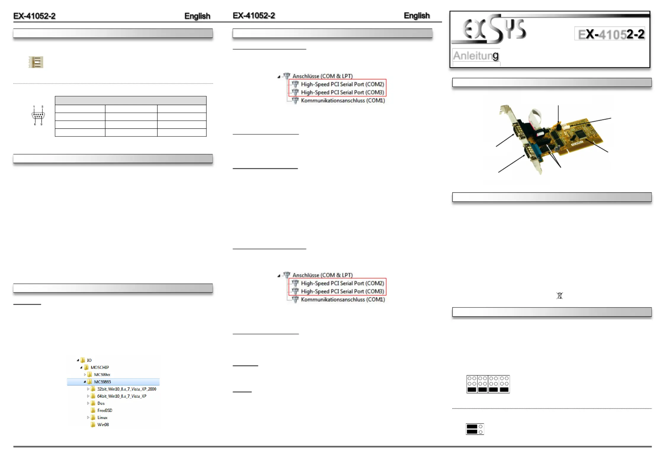
JUMPEREINSTELLUNG & ANSCHLÜSSE
Die EX2 ist eine 32Bit PCI Seriell RS232 Karte mit zwei seriellen FIFO 16C550 Ports, -41052---
für den Anschluss von HighSpeed seriellen RS232 Peripherie Geräten (z.B. Modem, Plotter --
usw.). Die EX2 nutzt den 16C550 UART Chipsatz, der die neueste HighSpeed-41052---
InterfaceTechnologie beinhaltet. Die Karte gewährleistet so eine sichere Datenübertragung -
und exzellente Performance von bis zu 115KBaud/s für jedes angeschlossene serielle Gerät!
Sie unterstützt den 32 und 64Bit PCI bzw. PCIX Bus mit 5 Volt und 3,3 Volt. Es ist nicht ---
möglich die I/O Adressen und Interrupts manuell einzustellen, da die Einstellungen der Karte
vom System (BIOS) und beim installieren des Betriebssystems automatisch vorgenommen
werden. Es besteht bei Bedarf die Möglichkeit, +5V oder +12V auf einen von vier möglichen
Pins der beiden 9 Pin Stecker zu legen (POS System).
BESCHREIBUNG & TECHNISCHE DATEN
AUFBAU
Kompatibilität:PCI oder PCIX, 33Mhz-
Betriebssysteme:DOS/ 98/ 2000/ XP/ Vista/ 7/ 8.x/ 10/ Server 20xx/ Linux
Anschlüsse:2x 9 Pin DSUB Stecker-
Lieferumfang:2, Treiber CD, Anleitung, Low Profile BügelEX-41052-
Zertifikate:FCC / RoHS / WEEE DE97424562 / WHQL
CE
CE
CE
CECE /
Mit der EX2 haben Sie die Möglichkeit +5V oder +12V auf einen der folgenden vier -41052-
Pins der Stecker und zu konfigurieren:S1 S2
Achtung! Nur konfigurieren wenn für das Peripheriegerät wirklich +5Volt oder +12Volt
benötigt wird. Für normale Anwendung den Jumper nicht verändern, sonst werden Ihre Geräte
beschädigt!
If JP9 is set to AUX the J5 must be connected with pc power
supply!
Please make sure you connect the plug in the right
direction! Never connect or release the plug while the
PC power is on!
S1: 9 Pin Stecker
Seriell Anschluss
Seriell Chip 16C550
mit 16Byte Buffer -
und PCIBridge-
S2: 9 Pin Stecker
Seriell Anschluss
J5: Stromanschluss
für PCNetzteil-
JP2 & JP3:
+5V oder +12V einstellbar auf
beide 9 Pin Seriell Stecker
JP9: Jumper für die Stromquelle
(Netzteil oder PCI Bus)
DB9M:
Serial 9 Pin DSUB serial male connector-
PinSignalPinSignalPinSignal
14DTR7RTSCDC
2RXD5GROUND8CTS
3TXD6DSR9 RI
JUMPERSETTING & CONNECTORS
HARDWAREINSTALLATION
If you are ready with the jumper settings, please proceed with the following installation instruc-
tions. Because there are large differences between PC’s, we can give you only a general installa-
tion guide for the EX2. Please refer to your computer’s reference manual whenever in -41052-
doubt.
1. Turn off the power to your computer and any other connected peripherals.
2.Remove the mounting screws located at the rear and/or sides panels of your Computer
and gently slide the cover off.
3.Locate an available PCI slot and remove its covers from the rear panel of your computer.
Make sure it is the right expansion slot for the card (see card description)
4.Align the card with the PCI slot, and then gently but firmly, insert the card. Make sure the
card is seated and oriented correctly. Never insert the card by force!
5. Then connect the card with a screw to the rear panel of the computer case.
6.Gently replace your computer’s cover and the mounting screws.
DRIVER INSTALLATION
1 +5V
2 GND
3 GND
4 +12V
J5:
DRIVER INSTALLATION
Anleitun
Vers. 1.2 / 16.11.15
E4105
Windows
After completing the hardware installation, the operating system will automatically the card and
install this! If the driver should not be installed automatically, insert the driver CD into you CD-
ROM drive (eg drive D:) and then open the folder „IO/MOSCHIP/MCS9865“. Please select the
folder with your operating system and install the driver (see Picture). Follow the hardware
assistant and finish the installation. Restart your PC in any case after installing the Important!
drivers.
CHECK INSTALLED DRIVER
Open the >Device manager<. Now you should see at „Ports (COM & LPT)“ the following new
entry's:
If you see this or a similar information the device is installed correctly.
CHANGE PORT NUMBER
If you like to change the port number for example COM3 to COM5, open the „Device Manager ”
click at „COM3”,Settings „”and then „Advance”. There you can change between COM3 till
COM256.
Windows Server 20xx
After completing the hardware installation, the operating system will automatically the card and
install this! If the driver should not be installed automatically, insert the driver CD into you CD-
ROM drive (eg drive D:) and then open the folder „IO/MOSCHIP/MCS9865“. Please select the
folder with your operating system and install the driver. Follow the hardware assistant and
finish the installation. Restart your PC in any case after installing the drivers.Important!
Use the following driver for the following Windows Server Version.
Windows Server 2003=XP Driver
Windows Server 2008=VISTA Driver
Windows Server 2008R2=Windows 7 Driver
Windows Server 2012=Windows 8 Driver
Windows Server 2012R2=Windows 10 Driver
CHECK INSTALLED DRIVER
Open the >Device manager<. Now you should see at „Ports (COM & LPT)“ the following new
entry's:
If you see this or a similar information the device is installed correctly.
CHANGE PORT NUMBER
If you like to change the port number for example COM3 to COM5, open the „Device Manager ”
click at „COM3”,Settings „”and then „Advance”. There you can change between COM3 till
COM256.
MS- DOS
Please read the manual on the driver CD. You will find the manual in the following folder
„IO/MOSCHIP/MCS9865/Dos“.
LINUX
Copy and unzip the file MCS9865_Linux.tar to your hard disk. The file is located on the driver
CD in the path „D:\IO\MOSCHIP\MCS9865\Linux “.Before installing the driver please read the
PDF File MCS9865_Linux_UM_Ver.1.1.
JP2 & JP3:
(S1 & S2)
+5V
+12V
DIS
Pin 4Pin 9Pin 8Pin 1
Achtung!Es darf pro Pin immer nur eine Spannung einge-
stellt werden!
+5V: +5V auf den jeweiligen Pin des Anschlusses
+12V: +12V auf den jeweiligen Pin des Anschlusses
DIS: Keine Spannung auf dem Anschluss (Werkseinstellung)
JP9:
JP9 gesetzt = +5 +12V kommt vom PCIBus (Werkseinstellung)auf PCIoder-
JP9 gesetzt = +5 oder +12V kommt vom PC Netzteilauf AUX
PAUXCI
+5V
+12V
Product specificaties
| Merk: | EXSYS |
| Categorie: | Niet gecategoriseerd |
| Model: | EX-41052-2 |
| Kleur van het product: | Grey, Yellow |
| Gewicht: | 200 g |
| Breedte: | 120 mm |
| Diepte: | 40 mm |
| Stroomvoorziening: | 3.3V/5V |
| Soort serieële aansluiting: | RS-232 |
| Certificering: | WHQL\r\nFCC, CE |
| Duurzaamheidscertificaten: | RoHS |
| Temperatuur bij opslag: | -40 - 75 °C |
| Intern: | Ja |
| Ondersteunt Linux: | Ja |
| Hostinterface: | PCI |
| Aansluiting(en): | 1 x 9 pin D-SUB |
| Ondersteunde server operating systems: | Windows Server 2003, Windows Server 2003 x64, Windows Server 2008, Windows Server 2008 R2, Windows Server 2008 x64 |
| Seriële poort(en): | 2 |
| Chipset: | MosChip MCS9865IV-AA |
| Overdrachtssnelheid: | 0.1152 Mbit/s |
| Bedrijfstemperatuur (T-T): | 0 - 55 °C |
| Relatieve vochtigheid in bedrijf (V-V): | 5 - 95 procent |
| Peripheral (Molex) power connectors (4-pin): | 1 |
| Output interface: | Serie |
Heb je hulp nodig?
Als je hulp nodig hebt met EXSYS EX-41052-2 stel dan hieronder een vraag en andere gebruikers zullen je antwoorden
Handleiding Niet gecategoriseerd EXSYS

4 December 2025
1 December 2025
1 December 2025
29 November 2025
26 November 2025
25 November 2025
13 November 2025
11 November 2025
10 November 2025
10 November 2025
Handleiding Niet gecategoriseerd
Nieuwste handleidingen voor Niet gecategoriseerd
9 Maart 2026
9 Maart 2026
9 Maart 2026
9 Maart 2026
9 Maart 2026
9 Maart 2026
9 Maart 2026
9 Maart 2026
9 Maart 2026
9 Maart 2026