Dormakaba RCI 3510LM Handleiding
Dormakaba
Niet gecategoriseerd
RCI 3510LM
Bekijk gratis de handleiding van Dormakaba RCI 3510LM (2 pagina’s), behorend tot de categorie Niet gecategoriseerd. Deze gids werd als nuttig beoordeeld door 45 mensen en kreeg gemiddeld 4.6 sterren uit 23 reviews. Heb je een vraag over Dormakaba RCI 3510LM of wil je andere gebruikers van dit product iets vragen? Stel een vraag
Pagina 1/2

INSTALLATION
RCI 3510LM
CABINET LOCK WITH LATCH MONITOR
ELECTRIC LOCK FOR SMALL ENCLOSURES
© 2020 dormakaba Canada Inc
www.dormakaba.us • Phone: 1.800.265.6630 • Fax: 1.800.482.9795 • E-mail: sales_RCI@dormakaba.comIS3510LM
PCN2016
R10-20GR-1
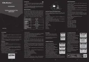
WIRING INSTRUCTIONS
NOTE: This lock requires some sort of external control.
1. Connecting wire must be of sufficient gauge to prevent line loss.
The 3510LM Cabinet Lock operates on either 12 or 24 VAC/DC
For 12 volt operation: connect a wire jumper from terminal 1 to 2 and also from terminal 3 to 4.
For 24 volt operation: connect one wire jumper from terminal 2 to 3.
2. With voltage jumpers installed, connect the positive (+) lead from the power supply to terminal 1.
Connect the negative(-) lead from the power supply to terminal 4.
For DC voltage, the supplied diode must be connected across terminals 1 and 4.
For AC voltage, terminal 1 and 4 connections are not polarity conscious. The diode is not required.
3 . The latch monitor feature indicates whether the door is closed/locked or open/unlocked.
The monitor switch contacts are rated 1 Amp @ 25V maximum.
Connect terminals 5 or 6 and 7 to suit N/O or N/C monitor requirements.
LM FEATURE
++
_ _
LATCH MONI R SWITCHTO
OUTPUT CONTACTS RATED
1 AM @ 25VP
12V JUMPER
CONNECTION
24V JUMPER
CONNECTION
+
-
Operating Voltage 12VDC 12VAC 24VDC 24VAC
Amps 0.25A 0.25A 0.12A 0.12A

MOUNTING INSTRUCTIONS
1. Two symbols are located on the latch that define fail locked or fail unlocked.
To set lock mode, align the latch symbol with the arrow on the lock.
Make sure to use the fail unlocked position for initial mounting and alignment.
Without power, the fail locked mode cannot open.
2. Using the cut-out template, mount the locking unit to the fixed portion of the cabinet or drawer with the four
#6 x 1-1/4” PH SMS screws.
Typical installations are shown below.
The locking unit and latch must be aligned as shown.
3. Peel the yellow side of the adhesive tape and apply to the back of the latch.
Engage latch into the mounted locking unit in the fail locked position.un
Peel white side of adhesive tape.
Close and open cabinet door or drawer.
The latch will be attached in the correct location.
For fail unlocked, simply secure the latch with the
four #6 x 1/2” PH SMS screws.
For fail locked turn the latch 180˚ and secure.
WasherWasher
Swing (Cupboard) MountSlide (Drawer) Mount
Apply Adhesive
Tape Here
Latch
L
C
Fold along dotted line on
fixed edge for surface mount
30.5mm
10mm
4.5mm
48mm
4.3mm
21mm
5mm
42mm
32mm
Cut-Out Template
Mounting Examples
Correct Alignment
Incorrect mounting
Correct Mounting Correct Mounting Correct Mounting
Fail Unlocked
Power to Lock
Fail Locked
Power to Unlock
Product specificaties
| Merk: | Dormakaba |
| Categorie: | Niet gecategoriseerd |
| Model: | RCI 3510LM |
Heb je hulp nodig?
Als je hulp nodig hebt met Dormakaba RCI 3510LM stel dan hieronder een vraag en andere gebruikers zullen je antwoorden
Handleiding Niet gecategoriseerd Dormakaba

9 Juli 2023

9 Juli 2023

9 Juli 2023

9 Juli 2023

9 Juli 2023

9 Juli 2023

9 Juli 2023

9 Juli 2023

9 Juli 2023

9 Juli 2023
Handleiding Niet gecategoriseerd
- IDance
- James
- Cygnett
- Whirlpool
- Dolmar
- Datalogic
- Goal Zero
- Dowco
- 70mai
- T-Spec
- Sagitter
- Alphacool
- YSI
- Biltema
- Barkan
Nieuwste handleidingen voor Niet gecategoriseerd

14 September 2025

14 September 2025

13 September 2025

13 September 2025

13 September 2025

13 September 2025

13 September 2025

13 September 2025

13 September 2025

13 September 2025