Dormakaba EAC Handleiding


Lees hieronder de 📖 handleiding in het Nederlandse voor Dormakaba EAC (10 pagina's) in de categorie Niet gecategoriseerd. Deze handleiding was nuttig voor 34 personen en werd door 2 gebruikers gemiddeld met 4.5 sterren beoordeeld

Pagina 1/10
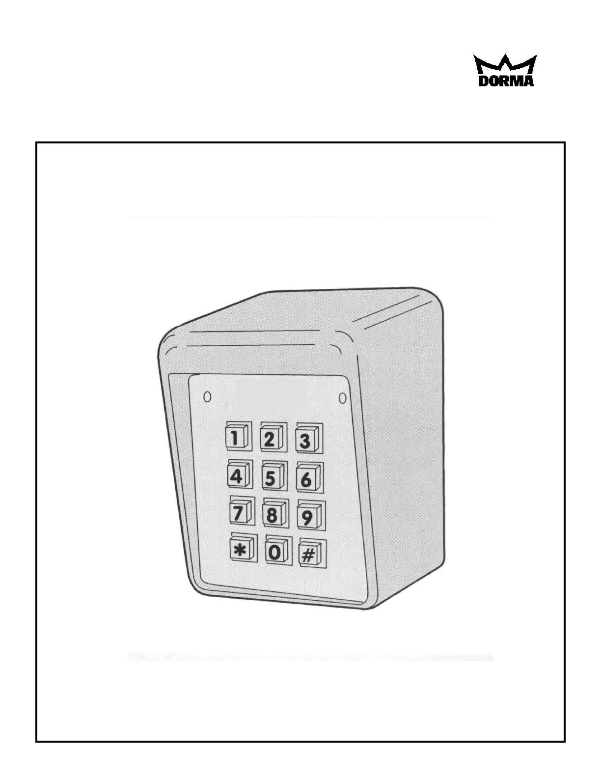
INSTALLATION INSTRUCTIONS
AC-225 KEYPAD
08105683 2/03
GENREAL
480 entry codes, from 1 to 6 digits in length, can be pro-
grammed. They can activate either, or both of the relay
outputs. Relay #1 has a 5 Amp capacity. Relay #2 has a
1 Amp capacity.
Two LED indicators show the status of the entry system.
The left LED lights red to indicate power, then turns
green when access is granted. The right LED lights yel-
low when the keypad is in "lockout" condition (from too
many incorrect code entries). The keypad's courtesy light
illuminates the keys for two minutes after any key is
pressed. An internal sounder beeps when each key is
pressed.
The DOOR SENSE/INHIBIT RELAY #1 input can be
used two ways. If used for "door position switch", the
switch on the door detects forced entry or door ajar situa-
tions. If used for "inhibit/disable", the input can be wired
to a "service" switch or automatic timer that will disable
the Relay #1 when required.
REQUEST-TO-ENTER/EXIT input can be wired to a
pushbutton or fire access keyswitch to provide codeless
entry for authorized personnel. In a door control applica-
tion, this input is also known as a request-to-exit. The
"anti-passback" feature prevents using the same code
twice before the programmed time elapses.
The ALARM SHUNT output activates when access is
granted. This output can be wired to shunt alarm con-
tacts on the access door/gate to prevent triggering of an
alarm when authorized access occurs.
Two solid state outputs, capable of switching 100 mA to
common, are programmable to signal forced entry, door
ajar, lockout, alarm circuit shunting, request-to-enter/exit
and keypad active conditions.
The AC-225 is powered from a 12-24 Volt AC or DC
source. Power can be obtained from the access device
or a separate power supply. The EEPROM memory
retains all entry codes and programming, even without
power.
SPECIFICATIONS
ELECTRICAL MECHANICAL
Voltage:12-24 Volts AC or DC Case dimensions:4.0" W x 5.5" H x 3.0" D
(AC supply must be transformer isolated)
Current:10 mA typical, 150 mA maximum ENVIRONMENTAL
Outputs:Relay #1 Temperature:-20°F to 130°F (-29°C to 54°C)
Form "C" 5 Amps @ 24 Volts maximum Humidity:5% to 95% non-condensing
Relay #2
Solid state outputs (Outputs #3 & #4)
Short-to-common 100 Ma
@ 30 VDC maximum
TACTILE
KEYPAD
YELLOW
"LOCKOUT"
INDICATOR
RED/GREEN
POWER/ACCESS
INDICATOR
NIGHT
LIGHT
T
ERMINAL BLOCK J4
P
OWER AND INPUTS
IKEYLOCK
TERMINAL
BLOCK J3
OUTPUTS
JUMPER JP1
REMOVE TO
REDUCE
BEEPER SOUND
JUMPER JP2
RESETS
MASTER CODE
2
INSTALLATION
To avoid damage to the unit from static discharges, con-
nect the EARTH GROUND terminal to a good earth-
grounding point. Suggested wiring size is 18 AWG for
earth ground and for power, up to 500ft. (use larger wire
for longer runs). Use22 AWG or larger (depending on the
load) for all other connections.
CAUTION: Do not ground either side of the power
inputs when using AC power.
Select a location for the keypad. For door access control
installations, mount the keypad near the controlled door.
For gate control installations, mount the keypad in clear
view of the gate, but far enough from the gate so the user
cannot touch the gate from the keypad.
WARNING: TO AVOID SERIOUS INJURY OR DEATH,
MAKE SURE THAT THE UNIT IS FAR ENOUGH FROM
THE GATE SO THAT THE USER CANNOT TOUCH
THE GATE WHILE OPERATING THE KEYPAD. HOW-
EVER, THE GATE MUST BE FULLY VISIBLE FROM
THE KEYPAD.
MOUNTING
The AC-225 keypad can be mounted directly to a wall or
flat surface. Use the appropriate fasteners to secure the
keypad's backplate to the mounting surface. When
mounting the keypad to a concrete wall, use concrete
wedge anchors or molly anchors.
EXPOSED MOUNTING
The AC-225 keypad can be mounted on a standard
pedestal or exterior frame assembly. Use four security
bolts and locking nuts to secure the keypad’s backplate to
the pedestal or exterior frame assembly.
Mounting Keypad Backplate
MOUNT BACKPLATE WITH
SECURITY BOLTS AND LOCKNUTS
PEDESTAL OR EXTERIOR
FRAME ASSEMBLY
USE CONCRETE
WEDGE ANCHORS
OR MOLLY ANCHORS
WALL MOUNTING
3


Product specificaties

Merk: Dormakaba
Categorie: Niet gecategoriseerd
Model: EAC

Heb je hulp nodig?

Als je hulp nodig hebt met Dormakaba EAC stel dan hieronder een vraag en andere gebruikers zullen je antwoorden


Handleiding Niet gecategoriseerd Dormakaba

Handleiding Niet gecategoriseerd

Nieuwste handleidingen voor Niet gecategoriseerd