Danfoss SVA-140B Handleiding
Danfoss Niet gecategoriseerd SVA-140B
Bekijk gratis de handleiding van Danfoss SVA-140B (4 pagina’s), behorend tot de categorie Niet gecategoriseerd. Deze gids werd als nuttig beoordeeld door 123 mensen en kreeg gemiddeld 4.0 sterren uit 8 reviews. Heb je een vraag over Danfoss SVA-140B of wil je andere gebruikers van dit product iets vragen? Stel een vraag
Pagina 1/4
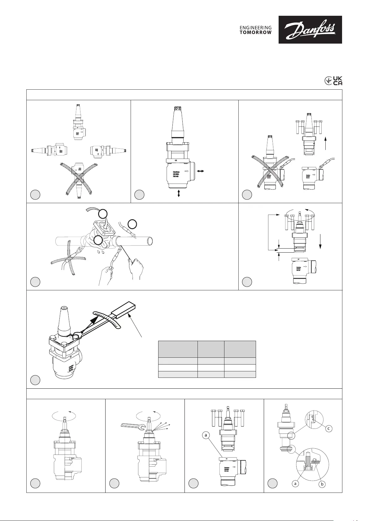
Installation guide
Shut-off valves
SVA-140B DN 50-100
148R9661
148R9661
© Danfoss | Climate Solutions | 2022.06
AN41292544562101-000101 | 1
Installation / Instalación / Installazione
Valve Size
Max. Nm
Nm máx.
Maks. (Nm)
Max. LB-feet
lb-ft máx.
Max. Lb-piedi
DN 50 - 65133 +/ -598 +/ -3.7
DN 8084 +/ -562 +/ -3.7
DN 100135 +/ -5100 +/ -3.7
Maintenance / Wartung / Entretien / Mantenimiento / Manutenzione
123
45
6
71098
Ag40 minimum 450 – 700 °C
6
5
3
089
0879
Info for UK customers only : Danfoss Ltd., 22 Wycombe End, HP9 1NB, GB
Імпортер:ТОВ з іі “Данфосс ТОВ” 04080, Київ 80, п/с 168, Україна
Product specificaties
| Merk: | Danfoss |
| Categorie: | Niet gecategoriseerd |
| Model: | SVA-140B |
Heb je hulp nodig?
Als je hulp nodig hebt met Danfoss SVA-140B stel dan hieronder een vraag en andere gebruikers zullen je antwoorden
Handleiding Niet gecategoriseerd Danfoss

7 November 2025
1 September 2025
1 September 2025
26 Augustus 2025
26 Augustus 2025
25 Augustus 2025
19 Augustus 2025
18 Augustus 2025
18 Augustus 2025
30 Juli 2025
Handleiding Niet gecategoriseerd
Nieuwste handleidingen voor Niet gecategoriseerd
23 Juli 2026
23 Juli 2026
23 Juli 2026
23 Juli 2026
23 Juli 2026
23 Juli 2026
22 Juli 2026
22 Juli 2026
22 Juli 2026
22 Juli 2026