Bosch PKB651F17 Handleiding
Bekijk gratis de handleiding van Bosch PKB651F17 (9 pagina’s), behorend tot de categorie Fornuis. Deze gids werd als nuttig beoordeeld door 9 mensen en kreeg gemiddeld 4.9 sterren uit 5 reviews. Heb je een vraag over Bosch PKB651F17 of wil je andere gebruikers van dit product iets vragen? Stel een vraag
Pagina 1/9

*9000750991* 9000750991 000306
Ø Montageanleitung
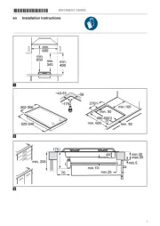
Ú Installation instructions
Þ Notice de montage
â Istruzioni per il montaggio
é Installatievoorschrift
× Monteringsvejledning
ì Instruções de montagem
Û Instrucciones de montaje
Ù Οδηγίες εγκατάστασης
ê Monteringsveiledning
ó Monteringsanvisning
Ý Asennusohje
î Инструкция по монтажу
Ö Montážní návod
ë Instrukcja montażu
ô Montaj kılavuzu
[
PLQ
:
5
=
PLQ
:
!
=
PLQ
PLQ
PLQ
[

de
Ø Montageanleitung
Das müssen Sie beachten
Elektrischer Anschluss: nur durch konzessionierten Fach-
mann. Bei Falschanschluss erlischt die Garantie.
Einbau: nur fachgerecht, bei Schäden haftet der Monteur.
Anschluss: das Gerät entspricht der Schutzklasse I und darf
nur in Verbindung mit Schutzleiteranschluss betrieben werden.
Installation: in der festverlegten elektrischen Installation ist eine
Trennvorrichtung in den Phasen nach den Errichtungsbestim-
mungen vorzusehen.
Unterbau: keine Kühlgeräte, Geschirrspüler, unbelüftete Backö-
fen, Waschmaschinen unterbauen.
Modular- /Kompakt-Geschirrspüler der gleichen Marke können
untergebaut werden. Arbeitsplattendicke dann mindestens 40
mm.
Wird unter dem Kochfeld ein Backofen eingebaut, muss die
Arbeitsplattendicke mindestens 20 mm betragen, in manchen
Fällen auch mehr. Beachten Sie die Hinweise in der Montagean-
leitung des Backofens.
Achten Sie darauf, dass vorstehende Teile wie z.B. das Netzan-
schlussgehäuse oder das Netzanschlusskabel nicht mit z.B.
einer Schublade kollidieren.
Zwischenboden: wenn die Kochfeldunterseite berührbar ist,
muss ein Zwischenboden montiert werden.
Fragen Sie im Fachhandel nach einem Zwischenboden als
Zubehör.
Wenn Sie einen eigenen Zwischenboden verwenden, muss der
Mindestabstand zum Netzanschluss des Gerätes 10 mm betra-
gen.
Arbeitsplatte: eben, waagrecht, stabil.
: Träger von elektronischen Implantaten!
Das Gerät kann Permanentmagnete enthalten, die elektronische
Implantate wie z.B. Herzschrittmacher oder Insulinpumpen
beeinflussen können. Deshalb bei der Montage einen Mindest-
abstand von 10 cm zu elektronischen Implantaten einhalten.
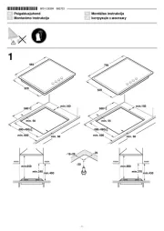
Möbel vorbereiten - Bild 1
Einbaumöbel: mindestens 90°C temperaturbeständig.
Ausschnitt: Nach Ausschnittarbeiten Späne entfernen.
Schnittflächen: hitzebeständig versiegeln.
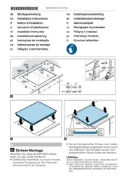
Befestigungsschienen anbringen - Bild 2
Geflieste Arbeitsplatten: untere Schraublöcher verwenden.
Arbeitsplatten aus Stein-Werkstoffen: Befestigungsschienen
ankleben.
Kochfeld anschließen und einsetzen - Bild 3
Vor Geräteanschluss Hausinstallation überprüfen.
Gerät ohne vormontierter Anschlussleitung: nur nach
Anschlussbild anschließen. Bei Bedarf beiliegende Kupferbrü-
cken montieren. Netzanschlussleitung: Typ H05 VV-F oder
höherwertig; erforderlichen Adernquerschnitt entspechend der
Strombelastung bestimmen. Ein Querschnitt < 1,5 mm2 ist nicht
zulässig!
Gerät mit vormontierter 5-adriger Anschlussleitung: nur ein
geschulter Kundendienst-Techniker darf die Anschlussleitung
austauschen.
Einsetzen: Anschlussleitung nicht einklemmen, nicht über
scharfe Kanten führen. Bei untergebautem Backofen Leitung an
den hinteren Ecken des Backofens zur Anschlussdose führen.
Hinweis: erscheint im Display des Gerätes —…‹‹ ist es falsch
angeschlossen. Gerät vom Netz trennen, Anschluss überprüfen.
Kochfeld ausbauen: Das Gerät spannungslos machen. Koch-
feld von unten herausdrücken.
en
Ú
Installation instructions
You must take note of the following
Electrical connection: To be carried out only by a licensed
electrician. Incorrect connection will invalidate the warranty.
Installation: To be carried out only by a professional. The fitter
is liable for any damage.
Connection: The appliance fulfils the requirements of protection
class I and may only be operated in conjunction with a safety
earth terminal.
Installation: In the permanent electrical installation, an all-pole
isolating switch must be provided in accordance with the
installation regulations. Identify the phase and neutral
conductors in the socket. The appliance may be damaged if it is
not connected correctly.
Installation underneath: Do not install refrigerators,
dishwashers, unventilated ovens or washing machines
underneath.
Modular/compact dishwashers of the same brand can be fitted
underneath. Work surface thickness must then be at least 40
mm.
If an oven is installed underneath the cooktop, the worktop must
be at least 20 mm thick, in certain cases even thicker. Note the
information in the installation instructions for the oven.
Make sure that projecting parts such as the mains housing or
the mains cable do not collide, e.g. with a drawer.
Intermediate floor: If the underside of the hob can be touched,
an intermediate floor must be fitted.
Ask your specialist retailer for an intermediate floor as an
accessory.
If you use your own intermediate floor, the minimum distance to
the mains connection of the appliance must be 10 mm.
Work surface: Level, horizontal, stable.
: Wearers of electronic implants!
The appliance may contain permanent magnets which may
affect electronic implants, e.g. heart pacemakers or insulin
pumps. Therefore, during installation, wearers of electronic
implants must maintain a minimum distance of 10 cm from the
appliance.
Preparing the units - Figure 1
Fitting unit: Heat resistant to at least 90°C.
Cut-out: After the cutting out work is complete, remove the
shavings.
Cut surfaces: Seal with heat-resistant material.
Attaching securing rails - Fig. 2
Tiled work surfaces: Use the lower screw holes.
Stone material work surfaces: Affix securing rails.
Connecting and fitting the hob - Fig. 3
Before connecting the appliance, check the household
installation.
Appliance without pre-fitted power cable: Only connect as
shown in the connection diagram. If necessary, fit the copper
bridges supplied. Power cord: Type H05 VV-F or higher;
determine the required wire cross-section depending on the
current rating. A cross-section of < 1.5 mm2 is not permissible.
Appliance with pre-fitted 5-wire power cable: The power cable
must only be replaced by a trained after-sales engineer.
Installing: Do not trap the power cable and do not route it over
sharp edges. If the oven is a built-under type, route the cable on
the rear corners of the oven to the socket.
Note: If —…‹‹ appears in the display, the appliance has not
been connected correctly. Disconnect the appliance from the
mains and check the connection.
Removing the hob: Disconnect the appliance from the power
supply. Push out the hob from below.

fr
Þ Notice de montage
Consignes à respecter
Branchement électrique : uniquement par un spécialiste agréé.
Toute erreur de branchement annule la garantie.
Encastrement : uniquement selon les règles de l’art,
l’installateur est responsable en cas de dommages.
Raccordement : l’appareil correspond à la classe de
protection I et ne doit être utilisé qu’avec un raccordement à la
terre.
Installation : dans l’installation à câblage fixe, un système
coupe-circuit dans les phases est à prévoir conformément aux
réglementations d’installation.
Sous le plan de travail : ne pas installer d’appareil réfrigérant ni
de lave-vaisselle, de four non ventilé ni de lave-linge.
Il est possible d’installer sous le plan de travail un lave-vaisselle
compact/modulaire de la même marque. Épaisseur minimum
du plan de travail 40 mm.
Si un four est installé sous la table de cuisson, l’épaisseur
minimale du plan de travail doit être de 20 mm, voire plus dans
certains cas. Respectez les consignes de la notice de montage
du four.
Veillez à ce que les parties saillantes telles que le boîtier
d’alimentation ou le câble d’alimentation n’entrent pas en
collision avec un tiroir, par exemple.
Plancher intermédiaire : s’il est possible de toucher le dessous
de la table de cuisson, il faut monter un fond intermédiaire.
Des planchers intermédiaires sont disponibles en tant
qu’accessoires dans le commerce spécialisé.
Si vous utilisez votre propre plancher intermédiaire, la distance
minimale par rapport à la prise secteur de l’appareil doit être de
10 mm.
Plan de travail : plat, horizontal, stable.
: Porteurs d'implants électroniques !
L'appareil peut contenir des aimants permanents qui peuvent
influer sur des implants électroniques, par ex. stimulateurs
cardiaques ou pompes à insuline. Pour cette raison, lors du
montage, respecter une distance minimum de 10 cm par
rapport aux implants électroniques.
Préparation du meuble - fig. 1
Meuble d'encastrement : résistant à une température d'au
moins 90°C.
Découpe : Enlever les copeaux après les travaux de découpe.
Chants de la découpe : les sceller de façon thermostable.
Montage des rails de fixation - fig. 2
Plans de travail carrelés : utiliser les trous de vis inférieurs.
Plans de travail en matériaux pierreux : coller les rails de
fixation.
Raccordement de la table de cuisson et mise en
place - fig. 3
Avant de raccorder l'appareil, vérifier l'installation domestique.
Appareil sans câble de branchement prémonté : ne le
raccorder que selon le schéma de raccordement. Si nécessaire,
monter les ponts en cuivre fournis. Cordon d'alimentation
secteur : type H05 VV-F ou supérieur ; déterminer la section des
fils requise en fonction de la charge électrique. Une section <
1,5 mm2 n'est pas autorisée !
Appareil avec câble de raccordement à 5 fils prémonté : seul
un technicien formé du SAV est habilité à remplacer le câble de
raccordement.
Mise en place : ne pas coincer le câble de raccordement, ne
pas le faire passer sur des arêtes coupantes. En cas de four
installé en dessous, faire passer le câble au niveau des coins
arrière du four jusqu'à la prise de raccordement.
Remarque : si —…‹‹ apparaît sur le display de l'appareil, c'est
qu'il est mal raccordé. Débrancher l'appareil du secteur, vérifier
le branchement.
Dépose de la table de cuisson : mettre l'appareil hors tension.
Sortir la table de cuisson en la poussant par le bas.
it
â
Istruzioni per il montaggio
Osservare quanto segue
Allacciamento elettrico: solo da parte di un tecnico autorizzato.
In caso di allacciamento scorretto decade la garanzia.
Montaggio: da eseguirsi esclusivamente in modo corretto; in
caso di danni la responsabilità verrà imputata a chi ha eseguito
il montaggio.
Collegamento: l'apparecchio rientra nella classe di protezione I
e può essere messo in funzione solo se collegato a un
conduttore di terra.
Installazione: durante la posa fissa dell'installazione elettrica, è
da prevedere un dispositivo di separazione nelle fasi
conformemente alle disposizioni dell'allestimento.
Sotto l'apparecchio: non è consentito incassare al di sotto
dell'apparecchio frigoriferi, lavastoviglie, forni non ventilati o
lavatrici.
Possono essere montate lavastoviglie modulari/compatte della
stessa marca. Lo spessore del piano di lavoro deve essere di
almeno 40 mm.
Se sotto il piano cottura viene installato un forno, lo spessore
del piano di lavoro deve essere di almeno 20 mm, in alcuni casi
anche di più. Prestare attenzione alle avvertenze presenti nelle
istruzioni per il montaggio del forno.
Prestare attenzione che le parti sporgenti, ad es. la scatola di
collegamento alla rete o il cavo per il collegamento elettrico,
non tocchino ad es. un cassetto.
Ripiano intermedio: se è possibile toccare il lato inferiore del
piano di cottura, è necessario montare un ripiano intermedio.
Richiedere presso un rivenditore specializzato un ripiano
intermedio come accessorio.
Se si utilizza un proprio ripiano intermedio, la distanza minima
dal collegamento elettrico dell'apparecchio deve essere di
10 mm.
Piano di lavoro: stabile, in piano e orizzontale.
: Portatori di impianti elettronici!
L'apparecchio può contenere magneti permanenti che possono
agire sugli impianti elettronici, quali ad es. pacemaker o pompe
di insulina. Pertanto al momento del montaggio i portatori di
impianti elettronici devono mantenere una distanza minima di
10 cm.
Preparazione del mobile: figura 1
I mobili da incasso: termostabili almeno fino a 90 °C.
Foro di incasso: Rimuovere i trucioli dopo i lavori di taglio.
Superfici di taglio: sigillare in modo refrattario.
Applicazione delle guide di fissaggio: figura 2
Piani di lavoro piastrellati: utilizzare le sedi per le viti inferiori.
Piani di lavoro in pietra: applicare le guide di fissaggio.
Montaggio e allacciamento del piano di cottura:
figura 3
Prima dell'allacciamento dell'apparecchio, controllare l'impianto
domestico.
Apparecchio senza cavo di allacciamento premontato:
attenersi soltanto allo schema di collegamento. Se necessario,
montare i ponticelli in rame forniti in dotazione. Cavo di
collegamento alla rete elettrica: modello H05 VV-F o superiore,
determinare la sezione dei cavi necessaria corrispondente al
carico di corrente. Una sezione < 1,5 mm2 non è consentita!
Apparecchio con cavo di allacciamento a 5 fili
precedentemente montato: le sostituzioni devono essere
effettuate esclusivamente da personale tecnico adeguatamente
istruito dal servizio assistenza tecnica.
Inserimento: fare in modo che il cavo non rimanga incastrato e
non passi su spigoli vivi. In caso di forni sottostanti, portare il
cavo alla presa di collegamento facendolo passare dall'angolo
posteriore del forno.
Avvertenze: se sul display dell'apparecchio compare —…‹‹
significa che l'allacciamento non è stato effettuato in modo
corretto. Staccare l'apparecchio dalla rete di alimentazione e
controllare l'allacciamento.
Smontaggio del piano di cottura: scollegare l'apparecchio
dalla rete elettrica. Estrarre il piano di cottura spingendolo dal
basso.
Product specificaties
| Merk: | Bosch |
| Categorie: | Fornuis |
| Model: | PKB651F17 |
Heb je hulp nodig?
Als je hulp nodig hebt met Bosch PKB651F17 stel dan hieronder een vraag en andere gebruikers zullen je antwoorden
Handleiding Fornuis Bosch

4 Juli 2025

4 Juli 2025
4 Juli 2025
16 Juni 2025
16 Juni 2025
16 Juni 2025

16 Juni 2025

16 Juni 2025

15 Juni 2025
15 Juni 2025
Handleiding Fornuis
- Igenix
- LERAN
- LAFE
- Foster
- Junker
- Saturn
- Scancool
- Lamona
- Kenmore
- Atlantic
- Ilve
- RGV
- Nedis
- Sauter
- Wolkenstein
Nieuwste handleidingen voor Fornuis

1 Augustus 2025
1 Augustus 2025
30 Juli 2025

30 Juli 2025

29 Juli 2025

29 Juli 2025

29 Juli 2025
29 Juli 2025
29 Juli 2025

29 Juli 2025