Bikemate 22970 Handleiding
Bikemate Fietscomputer 22970
Bekijk gratis de handleiding van Bikemate 22970 (2 pagina’s), behorend tot de categorie Fietscomputer. Deze gids werd als nuttig beoordeeld door 87 mensen en kreeg gemiddeld 4.5 sterren uit 8 reviews. Heb je een vraag over Bikemate 22970 of wil je andere gebruikers van dit product iets vragen? Stel een vraag
Pagina 1/2
(j) max. 30 cmmax. 30 cm
max. 60 cm
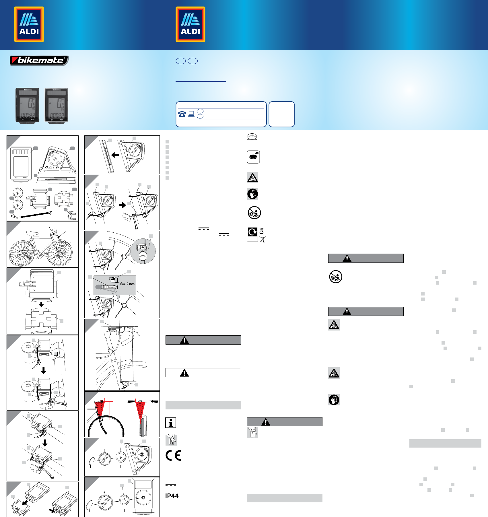
Scope of delivery
ABicycle computer
BBracket for bicycle computer
CRubber base for bracket
DSensor
ERubber base for sensor
FMagnet with magnet holder
G2 x button cell (2 x type CR 2032)
H6 x cable tie
Technical data
Bicycle computer, wireless with solar
Item No.: 90305
Batch: PO30000529
Model number: 22970
Power supply:
Operating voltage: 3 V
Sensor button cell: 3 V / Type: CR2032
Bicycle computer button cell: 3 V / Type:
CR2032
Protection type: IP44 (splashproof)
Transmission frequency and transmission power
Bicycle computer: Frequency band: 12 5 kHz ± 10 kHz
Sensor: Frequency band: 125 kHz ± 10 kHz
Maximum transmittable power: < 5 dBm
Weight: approx. 72 g (incl. accessories)
Bicycle computer measurements:
approx. 6.3 x 4 x 1.5 cm (L x W x D)
Date of production: 2019
Guarantee: 3 years
1. Introduction
Explanation of symbols
The following symbols and signal words are used in
these operating instructions, on the bicycle comput-
er or on the packaging.
WARNING!
This signal symbol/word indicates a hazard with a
medium level of risk which, if not avoided, may re-
sult in death or serious injury.
CAUTION!
This signal symbol/word indicates a hazard with a
low level of risk which, if not avoided, may result in
minor or moderate injury.
NOTE!
This signal word warns of possible property damage.
This symbol provides you with useful
additional information about operation.
This symbol indicates potential danger to
children.
Conformity declaration (see Chapter
“Conformity declaration”): Products that
are marked with this symbol fulfil all
applicable Community regulations of the
European Economic Area.
This symbol means direct current.
This symbol indicates the Protection
Class IP44 (protection against splashing
water from all sides).
This sign indicates how the button cell is
inserted.
INCLUDED
BATTERY
This symbol indicates that batteries are
included in the necessary scope of deliv-
ery.
This symbol indicates potential danger
in relation to explosions.
This symbol indicates potential danger
from handling batteries / rechargeable
batteries.
0-5
DANGER if swallowed
This symbol indicates dangers of swal-
lowing batteries.
Widely
Recycled
These symbols inform you about the
disposal of the packaging and prod-
uct.
2. Intended use
The bicycle computer is exclusively designed for
displaying and collecting information (e.g. average
speed, time etc.) while using a bicycle. It is only
intended for private use and is not suitable for the
commercial sector. Only use the bicycle computer as
described in these operating instructions. Any other
use is considered to be improper use and may result
in property damage or even personal injury. No lia-
bility is assumed for damage or injury resulting from
non-observance of these operating instructions or
improper use.
3. Safety instructions
Read the safety instructions thor-
oughly.
This bicycle computer can be used
by children from the age of eight
and above, as well as by persons
with impaired physical, sensory
or mental capabilities or a lack
of experience and knowledge, if
they are supervised or have been
briefed on the safe use of the fore-
arm trainer and the resulting haz-
ards. Children are not permitted
to play with the bicycle computer.
Cleaning and user maintenance
must not be performed by children
without supervision.
WARNING!
DANGER! RISK OF DEATH
AND INJURY.
Keep children away from packaging ma-
terial. Danger of suffocation, amongst other things!
The bicycle computer contains small parts. Children
can swallow these while playing and choke on
them. Keep the small parts away from children.
DANGER FROM BUTTON CELLS!
The button cell operation occurs with button cell
type CR 2032.
NOTE!
4. Risk of damage!
- Improper handling of the bicycle computer can
lead to damage.
- Operate the bicycle computer in an ambient tem-
perature of between -10° C and +50° C.
- Do not expose the bicycle computer to any perma-
nent moisture.
- Avoid dust, heat and long-lasting direct sunlight
- Never repair the bicycle computer yourself. In case
of technical problems, contact the service address
provided on the guarantee card.
- If the button cell compartment can no longer be
closed securely with the housing lid, dispose of
the bicycle computer as described in the “Disposal”
chapter.
- To avoid premature depletion of the button cell,
the magnet should not be directly in contact with
the sensor while the bike is left standing for a
longer period of time. Please remove the button
cells, if the bicycle computer is not being used for
a longer period of time.
5. Safety instructions regarding
button cells:
WARNING!
THERE IS A RISK OF INJURY!
0-5
DANGER if swallowed
- Button cells should be stored where
they are inaccessible for children.
Button cells may be fatal if swal-
lowed, so this bicycle computer and
its button cells must be stored out of reach for
small children.
WARNING!
EXPLOSION HAZARD: With im-
proper replacement of the button
cells.
- Button cells to be replaced may only be replaced
with the same type of button cells. Pay attention
to the correct polarity, when replacing the button
cells. If necessary, clean the button cell and the
contacts of the bicycle computer prior to insertion.
EXPLOSION HAZARD: Never re-
charge non-rechargeable button cells, do
not short-circuit and/or open them. This
may result in overheating, risk of fire or bursting.
ATTENTION! Leaked or damaged but-
ton cells may cause acid burns if they
come into contact with skin. Do not
touch leaked button cells with bare hands; there-
fore, ensure that you wear appropriate protective
gloves in such a case!
- If a button cell has been swallowed, please consult
a doctor without delay.
- Only use CR 2032 type button cells from the same
manufacturer for the sensor and bicycle computer.
- Store button cells in a dry and cool, not damp,
place.
- Never throw button cells into fire. Explosion haz-
ard
- Never expose button cells to excessive heat. In-
creased risk of leakage!
- Do not deform button cells. Risk of explosions and
possible injuries to persons.
- Disposable button cells also lose part of their ener-
gy during storage.
- Remove the button cells if the bicycle computer is
not in use.
- Immediately remove depleted button cells from
the bicycle computer and dispose of them cor-
rectly with your local collection centre.
- Store disposable button cells separately from
discharged batteries, in order to avoid mix-ups.
6. Information about solar cells
This bicycle computer is fitted with solar cells,
which convert light energy into electric current.
This extends the service lift of the button cell. But-
ton cells are nevertheless required for the energy
supply in case of darkness and those of the sensor.
7. Check bicycle computer
Prior to initial use, check whether the bicycle com-
puter is complete and undamaged.
8. Assembly
8.1 Assembly point on the bicycle /
There are 2 assembly points for the computer and 1
assembly point for the sensor/magnet, see Fig. (a).
8.2 Assemble bracket and bicycle
computer
Assembly on the stem / Fig. (b-c)
Insert the rubber base C under the bracket of the
bicycle computer B.
Place the bracket B with the rubber base C on
the stem (Assembly Point (1)) and insert two ca-
ble ties H through the designated guides on the
bracket B. Pull the cable ties H tightly, so that
the entire bracket is firmly attached. Cut off the
excess ends of both cable ties H with scissors. The
bracket is now assembled.
Assembly on the handlebar stem / Fig. (d)
Place the bracket B with the rubber base C on
the handlebar stem (Assembly Point (2)) and
insert two cable ties H through the designated
guides on the bracket B. Pull the cable ties H
tightly, so that the entire bracket is firmly attached.
Cut off the excess ends of both cable ties H with
scissors. The bracket is now assembled.
Assembly of the bicycle computer / Fig. (e)
Slide the bicycle computer A onto the bracket
B until it clicks into place. To remove the bicycle
computer from the bracket, press the locking hook
downwards and pull the bicycle computer out of
the bracket.
8.3. Assemble the sensor and
magnet
Assembly of the sensor / Fig. (f-g)
Place the rubber base E on the sensor D.
NOTE!
The battery cover of the sensor must be facing
away from the spokes during assembly.
Hold the sensor D with the rubber base E on
the fork tube (Assembly Point (3)) and insert two
cable ties H through the designated guides on the
sensor D. Pull the cable ties H tightly, so that the
rubber base E and sensor D are firmly attached.
Cut off the excess ends of both cable ties H with
scissors. The sensor is now assembled.
4-colour process (CYMK)
ILLUSTRATOR & PHOTOSHOP Shadow
K:100M:100 Y:100
1
AD
E
B C
F
G
H
(a) (1)
(2)
(3)
(b) B
C
(c)
C
C
B
B
H
H
(d)B
B
H
H
C
C
(e) AA
B
(f)ED
(g)
H
E E
D D
H
(h)
D
F
F
D
(h-1)
(h-2)
(i)
D
A
max. 60 cm
90°
(k)
Coin
Buon cell cover
3V (CR2032)
DG
(l)
Coin
Buon cell cover
3V (CR2032)
A
G
User
Manual
BICYCLE COMPUTER
WIRELESS WITH SOLAR
PRODUCED IN CHINA FOR:
ALDI STORES LTD. PO BOX 26, ATHERSTONE
WARWICKSHIRE, CV9 2SH.
ALDI STORES (IRELAND) LTD.
PO BOX 726, NAAS, CO. KILDARE.
YEAR
WARRANTY
3
AFTER SALES SUPPORT 90305
00800 / 68546854
(free of charge, mobile networks may vary)
MODEl:
22970/PO30000529 04/2020
IE
GB IE
GB
Great care has gone into the manufacture of this product and it should
therefore provide you with years of good service when used properly. In
the event of product failure within its intended use over the course of the
first 3 years after date of purchase, we will remedy the problem as quickly
as possible once it has been brought to our attention. In the unlikely event
of such an occurrence, or if you require any information about the product,
please contact us via our helpline support services, details of which are to be
found both in this manual and on the product itself.
Product specificaties
| Merk: | Bikemate |
| Categorie: | Fietscomputer |
| Model: | 22970 |
Heb je hulp nodig?
Als je hulp nodig hebt met Bikemate 22970 stel dan hieronder een vraag en andere gebruikers zullen je antwoorden
Handleiding Fietscomputer Bikemate

9 Juni 2023
9 Juni 2023
9 Juni 2023
9 Juni 2023
9 Juni 2023
9 Juni 2023
29 Mei 2023
Handleiding Fietscomputer
Nieuwste handleidingen voor Fietscomputer
23 Juli 2026
20 Juli 2026
14 Juni 2026
15 Mei 2026
11 Mei 2026
16 Maart 2026
15 Maart 2026
14 Maart 2026
5 December 2025
23 September 2025