Advantech PCM-3610 Handleiding
Advantech
Niet gecategoriseerd
PCM-3610
Bekijk gratis de handleiding van Advantech PCM-3610 (8 pagina’s), behorend tot de categorie Niet gecategoriseerd. Deze gids werd als nuttig beoordeeld door 2 mensen en kreeg gemiddeld 4.8 sterren uit 1.5 reviews. Heb je een vraag over Advantech PCM-3610 of wil je andere gebruikers van dit product iets vragen? Stel een vraag
Pagina 1/8


3PCM-3610 User's Manual
Module l/O addresses (SW1 and SW2)Module l/O addresses (SW1 and SW2)
Module l/O addresses (SW1 and SW2)
Range (hex) Switch position
1 2 3 4 5 6
200 - 207 O O O O O O
208 - 20F ●O O O O O
2E8- 2EF ●O●●●0
* 2F8 - 2FF (COM2) ●●●●●0
3E8 - 3EF ●O● ● ● ●
* 3F8 - 3FF (COM1) ● ● ● ● ● ●
O = 0n ● = 0ff * = defaults
NOTE: Switches 1-6 control the PC bus address lines
as follows:
SwitchSwitch
SwitchSwitch
Switch 1 2 3 4 5 6
LineLine
LineLine
Line A3 A4 A5 A6 A7 A8
Interrupt level-lRQ (JP2 and JP3)
You can set each port for any interrupt level from 3 to 9,
except 8. Jumper JP2 controls Ch. 1, and JP3 controls Ch.
2. Simply short the pins on the jumper corresponding to the
interrupt level (see figure below).
JP2 (Ch 1, COM1) IRQ JP3 (Ch, 2, COM2) IRQ
If you use the ports as standard COM1 and COM2, you will
need to set Channel 1 to IRQ 4 and Channel 2 to IRQ 3.
Note: If your CPU module or card has serial intefface
ports, you wiD need to adjust the 1/0 port
addresses (or disable the ports) to avoid
conflicts.
Connector pin assignments
You access the PCM-361 0’s ports through two extemal
male DB-9 connectors. Ground pins are not connected to
the DB-9 connector housing for the sake of isolation. With
channel 1 you must attach the external cable to the proper
proper connector (JP7 or JP8) depending on whether you
are using RS-232 or RS-485. See page 2 for details.
RS-422/485 pin assignments appear below:
RS~85RS~85
RS~85RS~85
RS~85
Pin descriptionPin description
Pin description
RS~22 1 TX-(DATA-) or send data - (DTE)
2 TX+(DATA+) or send data + (DTE)
3 RX+ or receive data + (DTE)
4 RX- or receive data - (DTE)
5 GROUND
6 RTS- or ready to send -
7 RTS+ or ready to send +
8 CTS+ or clear to send +
9 CTS- or clear to send -
RS-232 pin assignments appear below:
RS-232RS-232
RS-232RS-232
RS-232
Pin descriptionPin description
Pin description
1 DCD receive line signal detector
2 RD received data
3 TD transmitted data
4 DTR dataterminal ready
5 GND ground
6 DSR data set ready
7 RTS request to send
8 CTS clear to send
9 Rl ring indicator
Product specificaties
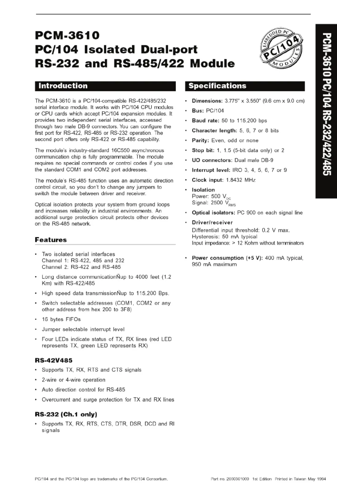
Merk: | Advantech |
Categorie: | Niet gecategoriseerd |
Model: | PCM-3610 |
Heb je hulp nodig?
Als je hulp nodig hebt met Advantech PCM-3610 stel dan hieronder een vraag en andere gebruikers zullen je antwoorden
Handleiding Niet gecategoriseerd Advantech
30 Juli 2025
30 Juli 2025
30 Juli 2025
30 Juli 2025
30 Juli 2025
30 Juli 2025
30 Juli 2025
30 Juli 2025
30 Juli 2025
30 Juli 2025
Handleiding Niet gecategoriseerd
- Konyks
- Zebra
- Creality3D
- Auriol
- Ezviz
- Teufel
- Oklahoma Sound
- Millecroquettes
- Altra
- Bolsey
- Boretti
- Gitzo
- Fisher Paykel
- LC-Power
- Mitsai
Nieuwste handleidingen voor Niet gecategoriseerd
30 Juli 2025
30 Juli 2025
30 Juli 2025
30 Juli 2025
30 Juli 2025
30 Juli 2025
30 Juli 2025
30 Juli 2025
30 Juli 2025
30 Juli 2025