Yingli Solar YLM-J 108 Cell M10 Handleiding

Yingli Solar Zonnepaneel YLM-J 108 Cell M10

Lees hieronder de 📖 handleiding in het Nederlandse voor Yingli Solar YLM-J 108 Cell M10 (11 pagina's) in de categorie Zonnepaneel. Deze handleiding was nuttig voor 25 personen en werd door 2 gebruikers gemiddeld met 4.5 sterren beoordeeld

Pagina 1/11
Y I N G L I S O L A R .C O M
This manual applies to photovoltaic modules (“PV modules”,
also commonly known as solar panels) manufactured by Yingli
Energy Development Company Limited (“Yingli Solar”), and
is explicitly written for qualified professionals (“Installer” or
“Installers”), including without limitation licensed electricians
and RAL Certified PV Installers.
I N T RO D U C T I O N
Thank you for choosing Yingli Solar as your PV module provider. We
appreciate your business! This manual contains important information
pertaining to the electrical and mechanical installation and maintenance
of PV modules, and contains safety information that you must read carefully and
be familiar with before handling, installing, and/or maintaining Yingli Solar PV
modules.
Yingli Solar does not assume responsibility and expressly disclaims liability for
losses, damages, or expenses arising out of, or in any way connected with this
Installation and User Manual. Yingli Solar assumes no responsibility for any
infringement of patents or other rights of third parties, which may result from
using Yingli Solar PV modules. No license is granted expressly or by implication
or under any patent or patent rights. The information in this manual is believed to
be reliable, but does not constitute an expressed or implied warranty. Yingli Solar
reserves the right to make changes to its PV modules and other products, their
specifications, or this manual without prior notice.
Yingli Solar and its subsidiaries are not liable for any damages caused by
inappropriate installation, use, or maintenance of Yingli Solar PV modules,
including without limitation damages, losses, and expenses caused by non-
observance of the instructions of this manual or caused by or in connection with
products of other manufacturers.
Yingli Solar PV modules are designed to meet the requirements for the standards
IEC 61215 IEC 61730 and , application class A. Modules rated for use in this
application class may be used in systems operating at greater than 50 V DC
or 240 W, where general contact access is anticipated. Modules qualified for
safety through and and within this application class are IEC 61730-1 IEC 61730-2
considered to meet the requirements for safety class II. In the course of the PV
module certification process, the compliance of this manual with the certification
requirements has been verified by an independent certification laboratory.
This Installation and User Manual is available in different languages. In cases of
discrepancy between versions, the English language version shall control.
Failure to comply with the requirements listed in this manual will invalidate the
Limited Warranty for PV Modules as provided by Yingli Solar at the time of sale to
the direct customer. Additional recommendations are provided to enhance safety
practices and performance results. Please provide a copy of this manual to the
PV system owner for their reference, and inform them of all relevant aspects of
safety, operation and maintenance.
S A F E T Y
General
You must understand and follow all applicable local, state, and federal regulations
and standards for building construction, electrical design, fire, and safety, and
must check with local authorities to determine applicable permitting requirements
before attempting to install or maintain PV modules.
Rooftop PV systems should only be installed on dwellings that have been
formally analyzed for structural integrity, and confirmed to be capable of handling
the additional weighted load of PV system components, including PV modules, by
a certified building specialist or engineer.
For your safety, do not attempt to work on a rooftop until safety
precautions have been identified and taken, including without
limitation fall protection measures, ladders or stairways, and
personal protective equipment (PPE).
For your safety, do not install or handle PV modules under adverse conditions,
including without limitation strong or gusty winds, and wet or frosted roof surfaces.
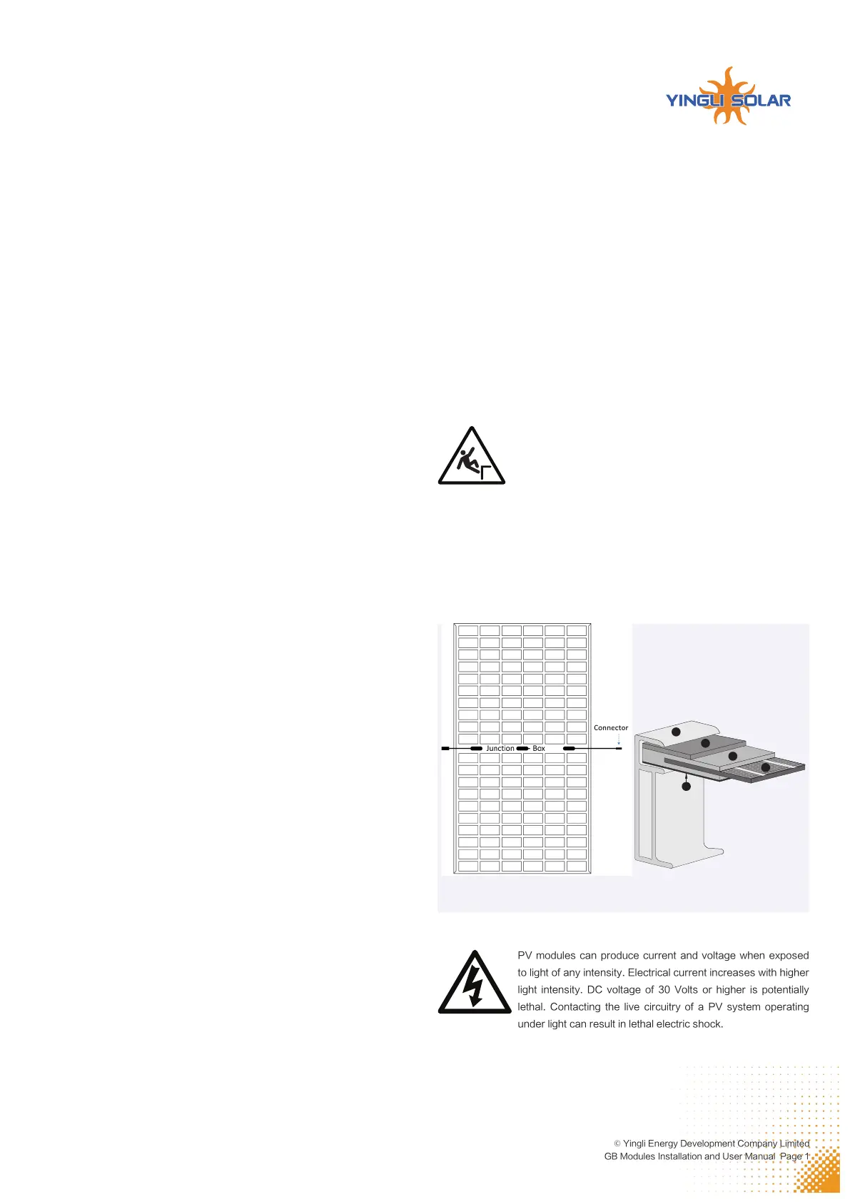
The flat-plate PV module construction consists of a laminated assembly of solar
cells encapsulated within an insulating material with a rigid glass surface and an
insulated substrate. The laminated assembly is supported by an aluminum frame
that is also used for installation the module. See Figure 1 for an illustration of the
PV module components.
Figure 1: Module components and cross-section of the laminated assembly
Electrical
1
1. Aluminum Frame
2. Glass
3. Encapsulating EVA
4. PV Cell
5. Backsheet
2
3
5
4
YINGLI SOLAR GB MODULES
Installation and User Manual
Revision date: Dec. 12th, 2022 | Applicable for IEC certified products | The second edition
Y I N G L I S O L A R .C O M
© Yingli Energy Development Company Limited
GB Modules Installation and User Manual Page 2
De-energize PV modules by removing them entirely from light or by covering
their front surface with an opaque material. Regard the safety regulations for
live electrical equipment when working with modules that are exposed to any
light. Use insulated tools and do not wear metallic jewelry while working with PV
modules.
In order to avoid arcing and electrical shock, do not disconnect electrical
connections under load. Faulty connections can also result in arcing and
electrical shock. Keep connectors dry and clean, and ensure that they are in
proper working condition. Never insert metallic objects into the connectors, or
modify them in any way in order to secure an electrical connection.
Do not touch or handle PV modules with broken glass, separated frames or
a damaged backsheet unless the PV modules are first disconnected and you
are wearing proper PPE. Avoid handling PV modules when they are wet unless
cleaning the PV modules as directed in this manual. Never touch electrical
connections that are wet without protecting yourself with insulated gloves.
Transport and Handling
Yingli Solar PV modules must be transported in the supplied packaging only and
kept in the packaging until they are ready to be installed. Protect pallets against
movement and exposure to damage during transportation. Secure pallets from
falling over. Do not exceed the maximum height of pallets to be stacked, as
indicated on the pallet packaging. Store pallets in a cool and dry location until the
PV modules are ready to be unpackaged.
Figure 2: Pallet of PV modules
Yingli Solar PV modules are heavy, and should be handled with care. PV modules
shall be handled at the frame; never use the junction box or cables as a grip. Do
not exert mechanical stress on the cables. Never step on PV modules or drop
or place heavy objects on them. Be careful when placing PV modules on hard
surfaces, and secure them from falling. Broken glass can result in personal injury.
PV modules with broken glass cannot be repaired and must not be used. Broken
or damaged PV modules must be handled carefully and disposed of properly.
For unpacking PV modules from the Yingli Solar supplied packaging, first remove
the pallet lid (after removing securing straps, if provided). Remove PV modules
one at a time by sliding them up the channel in the package (see Figure 3). You
may need to secure the remaining PV modules in the pallet packaging to prevent
them from falling over.
Figure 3: Removing PV modules from a pallet
Check PV modules for damage due to transportation before they are installed;
do not install damaged modules. Contact the company you purchased the Yingli
Solar PV modules from in order to obtain information on making claims for
defective PV modules.
PV module surfaces are susceptible to damage that could affect the performance
or safety of the PV module; do not damage or scratch the PV module surfaces,
and do not apply paint or adhesive to any of the surfaces, including the frame. For
your safety, do not disassemble or modify Yingli Solar PV modules in any way.
Doing so may degrade performance or cause irreparable damage and will void
any applicable warranties.
If it is necessary to store PV modules prior to installation, the PV modules should
remain inside the packaging and protected from exposure that could compromise
the durability of the packaging.
Fire
Yingli Solar PV Modules have a Class C fire resistance rating in accordance with
the IEC 61730-2 certification. When PV modules are mounted on rooftops, the
roof must have a fire resistant covering suitable for this application. PV modules
are electrical generating devices that may affect the fire safety of a building.
The use of improper installation methods and/or defective parts may result in the
unexpected occurrence of an electrical arc during operation. In order to mitigate
the risk of fire in this event, PV modules should not be installed near flammable
liquids, gases, or locations with hazardous materials.
In the event of a fire, PV modules may continue to produce a dangerous voltage,
even if they have been disconnected from the inverter, have been partly or
entirely destroyed, or the system wiring has been compromised or destroyed.
In the event of fire, inform the fire crew about the particular hazards from the PV
system, and stay away from all elements of the PV system during and after a fire
until the necessary steps have been taken to make the PV system safe.
A P P L I C A T I O N I N F O R M A T I O N
Application Restrictions
Yingli Solar PV modules must be mounted on appropriate installation structures
positioned on suitable buildings, the ground, or other structures suitable for PV
modules (e.g. carports, building facades or PV trackers). PV modules must not
be mounted on moving vehicles of any kind. Yingli Solar PV modules must not be
installed in locations where they could be submerged in water.
Yingli Solar PV modules must not be sited in locations where aggressive
substances such as salt or salt-water, or any other type of corrosive agent, could
affect the safety and/or performance of the PV modules. Although some types
of Yingli Solar PV modules have passed the IEC 61701 salt-mist corrosion test
with a salt concentration of 5% by weight, galvanic corrosion can occur between
the aluminum frame of the PV module and installation or grounding hardware if
such hardware is comprised of dissimilar metals. Yingli Solar recommends that
only stainless steel and aluminum metal directly contact PV modules in seaside
installations to limit corrosion.
Artificially concentrated light must not be directed on Yingli Solar PV modules.
Design Recommendations
Yingli Solar recommends that PV modules be mounted at a minimum tilt angle of
10 degrees to allow for proper self-cleaning from normal rain showers.
Partial or complete shading of a PV module or modules can significantly reduce
system performance. Yingli Solar recommends minimizing the amount of shade
throughout the year to increase the amount of energy produced by the PV
modules.
Lightning protection is recommended for PV systems that are to be installed in
locations with high probability of lightning strikes.
High system voltages could be induced in the event of an indirect lightning strike,
which could cause damage to PV system components. The open area of wire
loops should be minimized, as shown in Figure 4, in order to reduce the risk of
Y I N G L I S O L A R .C O M
© Yingli Energy Development Company Limited
GB Modules Installation and User Manual Page 3
Figure 4: Wire loop design recommendation
Series iring ( oltage dditive)w v a
Parallel iring ( urrent dditive)w c a
Fully engage and lock
Cap
+
lightning induced voltage surges.
E L E C T R I C A L IN S T AL L A T IO N
Electrical Configuration
Under normal conditions, a photovoltaic module is likely to experience conditions
that produce more current and/or voltage than reported at Standard Test
Conditions (STC: 1000 W/m2, AM 1.5, and 25℃ cell temperature). The short-
circuit current (ISC) should be multiplied by a factor of 1.25 and the open-circuit
voltage (VOC) should be multiplied by a factor of up to 1.25 based on the lowest
ambient temperature recorded for the installation location when determining
component voltage ratings, conductor current ratings, fuse sizes, and size of
controls connected to the PV output.
Voltages are additive when PV modules are connected directly in series, and
module currents are additive when PV modules are connected directly in parallel,
as illustrated in Figure 5. PV modules with different electrical characteristics must
not be connected directly in series. The use of suitable third-party electronic
devices connected to PV modules may enable different electrical connections
and must be installed according to the manufacturer’s specified instructions.
Figure 5: Electrical diagrams of series and parallel wiring
The maximum number of PV modules that can be connected in a series string
must be calculated in accordance with applicable regulations in such a way that
the specified maximum system voltage of the PV module and all other electrical
DC components will not be exceeded in open-circuit operation at the lowest
temperature expected at the PV system location.
An appropriately rated overcurrent protection device must be used when the
reverse current could exceed the value of the maximum fuse rating of the module.
An over current protection device and anti-reflection diode module are required
for each series string if more than two series strings are connected in parallel.and
reverse polarity is forbidden.
Cables and Wiring
Yingli Solar PV modules are provided with two (2) stranded, sunlight resistant
output cables that are terminated with PV connectors ready for most installations.
The positive (+) terminal has a female connector while the negative (-) terminal
has a male connector. The module wiring is intended for series connections [i.e.
female (+) to male (-) interconnections], but can also be used to connect suitable
third-party electrical devices that may have alternative wiring configurations so
long as the manufacturer’s instructions are followed.
Use field wiring with suitable cross-sectional areas that are approved for use at
the maximum short-circuit current of the PV module. Yingli Solar recommends
installers use only sunlight resistant cables qualified for direct current (DC) wiring
in PV systems. The minimum wire size should be 4mm 2.
Table 1: Required minimum field wiring specifications
Testing Standard Wire Size Temperature Rating
Required Minimum Field Wiring EN 50618 4 mm2- 40 C to + 90º ºC
Cables should be fixed to the installation structure in such a way that mechanical
damage of the cable and/or the module is avoided. Do not apply stress to the
cables. Do not bend cables to a bending radius of less than 40mm. For fixing, use
appropriate means, such as sunlight resistant cable ties and/or wire management
clips specifically designed to attach to the PV module frame. While the cables are
sunlight resistant and waterproof, where possible, avoid direct sunlight exposure
and water immersion of the cables.
Connectors
Keep connectors dry and clean, and ensure that
connector caps are hand tight before connecting the
modules. Do not attempt making an electrical connection
with wet, soiled, or otherwise faulty connectors.
Avoid sunlight exposure and water immersion of the
connectors. Avoid connectors resting on the ground or roof surface.
Faulty connections can result in arcs and electrical shock. Check that all electrical
connections are securely fastened. Make sure that all locking connectors are
fully engaged and locked.
Modules must not be interconnected using connectors from different
manufacturers and / or of different types. If modules having such different
connectors need to be interconnected, a qualified professional may replace
connectors according to the manufacturers’ specified instructions such that an
interconnection can be made with connectors from the same manufacturer and
the same type.
Figure 6: Series interconnection of a male (-) and female (+) connector
Bypass Diodes
The junction boxes used with Yingli Solar PV modules (not Smart Hot Spot Free
module) contain bypass diodes wired in parallel with the PV cell strings. In the
case of partial shading, the diodes bypass the current generated by the non-
shaded cells, thereby limiting module heating and performance losses. Bypass
diodes are not overcurrent protection devices.
Bypass diodes divert current from the cell strings in the event of partial shading.
See Figure 7-1 for a diagram showing how the cell strings are electrically
connected with the diodes.
Every piece of cells from Yingli Smart Hot Spot Free module parallels a diode,
with a cell is covered by shade or occurs an excepion, the paralleled diode can
bypass this cell, thus avoid hot spot, and can retain the maximum power output.
Bypass diodes divert current from a cell in the event of partial shading, See
figure 7-2 for a diagram showing how the cells are electricallly connected with
the diodes.


Product specificaties

Merk: Yingli Solar
Categorie: Zonnepaneel
Model: YLM-J 108 Cell M10

Heb je hulp nodig?

Als je hulp nodig hebt met Yingli Solar YLM-J 108 Cell M10 stel dan hieronder een vraag en andere gebruikers zullen je antwoorden


Handleiding Zonnepaneel Yingli Solar

Handleiding Zonnepaneel

Nieuwste handleidingen voor Zonnepaneel