Xantech HL85 Handleiding


Lees hieronder de 📖 handleiding in het Nederlandse voor Xantech HL85 (4 pagina's) in de categorie Niet gecategoriseerd. Deze handleiding was nuttig voor 16 personen en werd door 2 gebruikers gemiddeld met 4.5 sterren beoordeeld

Pagina 1/4
MODEL
HL85
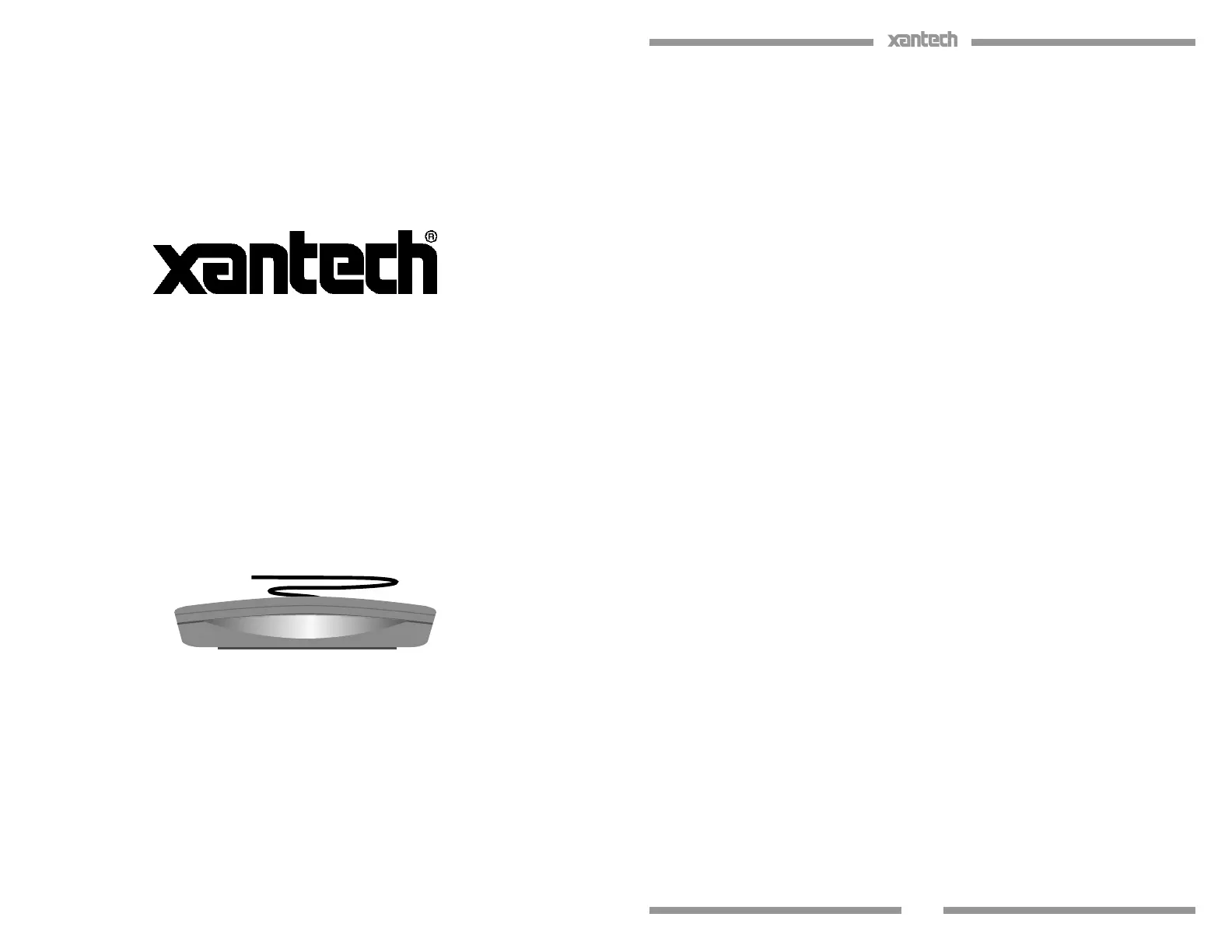
Hidden Link™ Shelf Top
Plasma/LCD/LED/CFL Friendly
IR Receiver
INSTALLATION INSTRUCTIONS
1
DESCRIPTION
The Hidden Link IR Receiver is a small shelf-top infrared repeater assembly. It
includes an IR receiver and a CB12 Connecting Block. The Hidden Link IR
Receiver is equipped with a 7-foot cable and a 3.5mm stereo mini plug, which
is plugged directly into the “IR RCVR” jack on the CB12. It can also be plugged
into the “AUX” or “IR RCVR” jack of other Xantech connecting blocks, such as
the models 789-44, CB60, and 791-44. The Hidden Link IR Receiver is
primarily intended for use in installations where the connecting block is within
reach of its 7-foot cable – as when installing the Hidden Link IR Receiver in a
cabinet where the controlled equipment is behind closed doors.
FEATURES
Very small package, only 2.00”L x 3.15”W x 0.70”H.
System testing red-talk-back LED.
Includes CB12 Connecting Block for easy system installation.
SPECIFICATIONS
Infrared carrier frequency bandwidth: 25 – 60 kHz.
Reception range: Up to 80 feet, depending on remote control output
strength and ambient conditions.
Nominal reception angle: 55 degrees o axis.
Cable requirements: See “INSTALLATION” below.
Max. transmission length: 1 mile using 18 gauge wire.
Maximum current output: 100mA
Drives IR emitters through Xantech Connecting Blocks, Controllers, etc.
Dimensions: 2.00”x3.15”x0.70” (51mm x 80mm x 18mm)
Power requirements: +12VDC, 20mA.
2
INSTALLATION
QUICK-START
A typical system will use an IR receiver, several emitters, and a power supply
all connected to a connecting block.
1. Connect the IR receiver to the “IR RCVR” port on the connecting block.
The ‘red’ connector is installed to the ‘red’ plug.
Note: In some extended distances, additional 3-conductor may be required and can be
connected to the terminals on the connecting block.
2. Connect the Emitters to the connecting block. The ‘yellow’ connector is
installed to the ‘yellow’ plug.
3. Connect the power supply to the connecting block.
4. Installation complete
LOCAL SYSTEM APPLICATION
In this system a 286D Dual Blink-IR Designer Emitter is shown connected to
the “OUT” jack. A single emitter could also be used, such as the model 282D or
283D. If expansion beyond two emitters is required, use a Xantech 789-44,
CB60, or 791-44 Connecting Block in place of the CB12. Do not use the CB12
in this case.
781ERGPS
To 120 VAC
(Unswitched)
Emitter
H
L Series
I
R
R
e
c
e
v
e
r
DVD
3
CABLE CONNECTIONS
HL2’s may also be used where the 7-foot cable is not long enough. Simply cut
o the mini plug, strip the leads and splice them to a 3-conductor extension
cable with a terminal block or other means. Then connect the extension cable
to the 3-terminal block on the CB12 as shown in the figure below.
3.5mm mini plug Signal Name Wire Color
TIP SIGNAL WHITE
RING GROUND BLACK
SLEEVE +12VDC RED
The 3-conductor inter-room cable (24 gauge up to 200’, 22 gauge up to 600’,
20 gauge up to 2000’, 18 gauge up to 5000’), is run to the main room.
While it is possible to make wired connections without the connecting block, it is
not recommended. The connecting block reduces installation time, helps to
eliminate errors, allows easy troubleshooting and permits easy system
upgrades later, if needed.
H
L Series
I
R
R
e
c
e
i
v
e
r
4
REMOTE ROOM APPLICATION
The CB12 Connecting Block, supplied with the Hidden Link IR Receiver, has a
three terminal input strip for connection of external infrared receivers should
you wish to control your equipment from other rooms.
The terminals are marked V G S. (V = +12V, G = Ground, and S = IR
Signal).
Make connections as shown in the gure below. Run a 3-conductor
cable (24 to 18 gauge wire, stranded or solid) from each remote room
to the VGS terminals of the CB12.
When you use a Hidden Link IR Receiver in a remote room, do not plug
in a power supply or use the “OUT” jack in the CB12, as shown in the
gure below.
You may use more IR receivers, connected in the same manner, up to
a maximum of 12.
PLACEMENT
The IR receiver should be located so that it is not directly facing a light source
such as lamps or displays (standard, LCD, and Plasma). When mounted near a
display, it should be ush to the display and away from light reections that may
occur.
781ERGPS
To 120 VAC
(Unswitched)
Emitter
H
L Series
I
R
R
e
c
e
i
v
e
r
HL2 IR Receiver
DVD
WL Series
5
TROUBLE SHOOTING:
1. Perhaps the most common problem you may encounter is stray IR
(infrared) or RF (radio frequency) interference preventing proper
operation of the controlled equipment.
Fluorescent, Compact Fluorescent, Neon or Halogen lights,
Neon Art, and light dimmers.
Direct or reected sunlight.
Infrared security sensors (active types).
RF radiation from TV sets that may be close to the Hidden Link
IR Receiver.
2. You can conrm the source of the interference by temporarily turning
o TV sets, isolating the Hidden Link IR Receiver from all sunlight and
turning o all lights, light dimmers and Infrared security systems. Then
check to see if the Hidden Link IR Receiver operates the component.
Sometimes interference will cause the red Talk-Back LED on
the front of the Hidden Link IR Receiver to blink dimly,
intermittently, or continuously.
The Talk-Back Led should only blink when you are sending
infrared commands to the Hidden Link IR receiver from a
remote control.
It may be necessary to move either the interfering source of the
Hidden Link IR Receiver to achieve proper operation.
3. If the Talk-Back LED or the 283D/286D Emitters do not blink when you
are sending IR commands to the Hidden Link IR Receiver from a
remote control, check the following:
Make sure the power supply is plugged securely into a live AC
electrical outlet.
Be sure the stereo mini plug of the Hidden Link IR Receiver is
plugged into the “IR RCVR” jack on the CB12 Connecting
Block, not into the “OUT” jack.
Check to see that all the mini plugs are properly seated into the
mini jacks on the CB12 Connecting Block.
4. If the 283D/286D Emitters blink, but the component does not respond,
reposition the emitters. They may not be located directly over the
component’s infrared receiving “window”. Consult the owner’s manual
of the unit or the manufacturer for the exact location of the infrared
“window”.


Product specificaties

Merk: Xantech
Categorie: Niet gecategoriseerd
Model: HL85

Heb je hulp nodig?

Als je hulp nodig hebt met Xantech HL85 stel dan hieronder een vraag en andere gebruikers zullen je antwoorden


Handleiding Niet gecategoriseerd Xantech

Handleiding Niet gecategoriseerd

Nieuwste handleidingen voor Niet gecategoriseerd