Vimar 20534 Handleiding
Vimar
Niet gecategoriseerd
20534
Bekijk gratis de handleiding van Vimar 20534 (6 pagina’s), behorend tot de categorie Niet gecategoriseerd. Deze gids werd als nuttig beoordeeld door 45 mensen en kreeg gemiddeld 4.9 sterren uit 23 reviews. Heb je een vraag over Vimar 20534 of wil je andere gebruikers van dit product iets vragen? Stel een vraag
Pagina 1/6

Viale Vicenza, 14
36063 Marostica VI - Italy
www.vimar.com
49400474B0 04 2111
EIKON
20534
ARKE’
19534
IDEA
16974
PLANA
14534
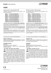
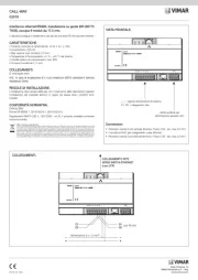
Attuatore con uscita a relè in scambio 6 A 120-230 V.
CARATTERISTICHE.
• Tensione nominale di alimentazione: BUS 29 V
• Assorbimento: 10 mA
• Uscita a relè in scambio
• Carichi comandabili a 120 - 230 V~ (contatto NO):
- carichi resistivi: 6 A (20.000 cicli)
- lampade a incandescenza: 6 A (20.000 cicli)
- lampade fluorescenti e lampade a risparmio energetico: 1 A (20.000 cicli)
- trasformatori elettronici: 4 A (20.000 cicli)
- trasformatori ferromagnetici: 6 A (20.000 cicli)
• Carichi comandabili a 120 - 230 V~ (contatti NO e NC):
- motori cos ø 0,6: 3,5 A (100.000 cicli)
• Morsetti:
- bus TP
- contatti relè (NC, C, NO)
CONFIGURAZIONE.
PER LE OPERAZIONI DI INSTALLAZIONE E CONFIGURAZIONE, VEDERE IL
MANUALE ISTRUZIONI DEL SISTEMA By-me Plus.
• Blocchi funzionali: 1
• Selezione del blocco funzionale (configurazione): durante la creazione dei gruppi,
quando viene richiesto di premere il pulsante del dispositivo:
- premere il pulsante, si accende il led;
- a led acceso, viene configurato il blocco funzionale; al termine dell’operazione il
led si spegne.
PARAMETRI.
• funzionamento monostabile o bistabile;
• ritardo attivazione e ritardo disattivazione: un valore compreso tra 0 e 200 espri-
me un tempo in secondi, un valore compreso tra 201 e 250 esprime un tempo in
minuti (per esempio 201 = 1 minuto, 202 = 2 minuti, ecc.);
.Funzionamento monostabile
Ritardo di attivazione: ritardo nella chiusura del contatto NO del relè dalla ricezio-
ne del comando di chiusura.
Ritardo di disattivazione: tempo di permanenza del relè con il contatto NO chiu-
so.
.Funzionamento bistabile
Ritardo di attivazione: ritardo nella chiusura del contatto NO del relè dalla ricezio-
ne del comando di ON.
Ritardo di disattivazione: ritardo nell’apertura del contatto NO del relè dalla rice-
zione del comando di OFF.
Nota.
Nel caso si crei un gruppo con più relè in modalità monostabile, impostare per
tutti gli stessi ritardi di attivazione e disattivazione e non inserire altri tipi di attuatori
all’interno dello stesso gruppo; in questo modo è possibile avere l’indicazione dello
stato del relè monostabile sul tasto di comando.
• Parametri di default: relè impostato in funzionamento bistabile con ritardo di atti-
vazione e disattivazione nullo.
SCENARI.
L’attuatore può appartenere a più scenari diversi e, per ognuno di essi, memorizzare
lo stato da richiamare all’attivazione dello scenario stesso.
REGOLE DI INSTALLAZIONE.
L’installazione deve essere effettuata da personale qualificato con l’osservanza delle
disposizioni regolanti l’installazione del materiale elettrico in vigore nel paese dove i
prodotti sono installati.
Il circuito di alimentazione dell’uscita a relè deve essere protetto contro i sovracca-
richi da un dispositivo, fusibile o interruttore automatico, con corrente nominale non
superiore a 10 A.
Rita ord
attivazione
Ritardo disattivazione
Comando
ON
Rita ord
attivazione
Comando
ON
Rita ord
disattivazione
Comando
OFF
ATTIVAZIONE DISATTIVAZIONE
MONOSTABILE
BISTABILE
FIGURA 1.
CONFORMITÀ NORMATIVA.
Direttiva BT.
Direttiva EMC.
Norma EN 50428.
Regolamento REACh (UE) n. 1907/2006 – art.33. Il prodotto potrebbe contenere
tracce di piombo.
A
A
B
B A B
Morsetti
bus TP
NO
C
NC
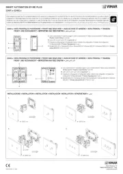
Legenda:
A: led
B: pulsante di configurazione
VISTA FRONTALE.
Idea Plana
Eikon
VISTA POSTERIORE.
Arké
A B
RAEE - Informazione agli utilizzatori
Il simbolo del cassonetto barrato riportato sull’apparecchiatura o sulla sua confezione indica che
il prodotto alla fine della propria vita utile deve essere raccolto separatamente dagli altri rifiuti.
L’utente dovrà, pertanto, conferire l’apparecchiatura giunta a fine vita agli idonei centri comunali
di raccolta differenziata dei rifiuti elettrotecnici ed elettronici. In alternativa alla gestione autonoma,
è possibile consegnare gratuitamente l’apparecchiatura che si desidera smaltire al distributore,
al momento dell’acquisto di una nuova apparecchiatura di tipo equivalente. Presso i distributori
di prodotti elettronici con superficie di vendita di almeno 400 m2 è inoltre possibile consegnare
gratuitamente, senza obbligo di acquisto, i prodotti elettronici da smaltire con dimensioni inferiori
a 25 cm. L’adeguata raccolta differenziata per l’avvio successivo dell’apparecchiatura dismessa al
riciclaggio, al trattamento e allo smaltimento ambientalmente compatibile contribuisce ad evitare
possibili effetti negativi sull’ambiente e sulla salute e favorisce il reimpiego e/o riciclo dei materiali
di cui è composta l’apparecchiatura.

Viale Vicenza, 14
36063 Marostica VI - Italy
www.vimar.com
49400474B0 04 2111
EIKON
20534
ARKE’
19534
IDEA
16974
PLANA
14534
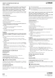
Actuator with changeover relay output 16 A - 230 V.
CHARACTERISTICS.
• Rated supply voltage: BUS 29 V
• Input: 10 mA
• Changeover relay output
• Controllable loads at 120-230 V~ (contact NO):
- resistive loads: 6 A (20.000 cycles)
- incandescent lamps: 6 A (20.000 cycles)
- fluorescent lamps and energy saving lamps: 1 A (20.000 cycles)
- electronic transformers: 4 A (20.000 cycles)
- ferromagnetic transformers: 6 A (20.000 cycles)
• Controllable loads at 120-230 V~ (contacts NO and NC):
- motors cos ø 0.6: 3,5 A (100.000 cycles)
• Terminals:
- TP bus
- relay contacts (NC, C, NO)
CONFIGURATION.
FOR THE OPERATIONS OF INSTALLATION AND CONFIGURATION, SEE
THE By-me Plus SYSTEM INSTRUCTIONS MANUAL.
• Functional blocks: 1
• Selecting the functional block (configuration): during group creation, when the
app requires pressing the device button:
- press the button, the LED will light up;
- with the LED on, the app will configure the functional block; at the end of this
operation the LED will go out.
PARAMETERS.
• one- or two-position stable operation;
• on delay and off delay: a value between 0 and 200 gives the time in seconds,
a value between 201 and 250 gives the time in minutes (for example 201 = 1
minute, 202 = 2 minutes, etc.);
.One-position stable operation
On delay: delay in closing the NO contact of the relay from receiving the close
command.
Off delay: time for which the relay has the NO contact closed.
Two-position stable operation.
On delay: delay in closing the NO contact of the relay from receiving the ON com-
mand.
Off delay: delay in opening the NO contact of the relay from receiving the OFF
command.
Note.
If a group is created with a number of relays in one-position stable mode, set for
all the same on and off delays and do not insert any other types of actuator in the
same group; in this way, it is possible to have the status of the one-position stable
relay indicated on the control button. For special requirements it is possible to use
the group depth (for example to switch on two-position stable relays or dimmers
with a single button).
• Default parameters: relay set on two-position stable operation with null on and off
delay.
SCENARIOS
The actuator can belong to multiple scenarios and, for each one of them, save the
status to retrieve when activating the scenario. For further details see the control
panel manual.
INSTALLATION RULES.
Installation should be carried out by qualified staff in compliance with the current
regulations regarding the installation of electrical equipment in the country where
the products are installed. The feeding circuit of the relay output must be protected
against overloads by a device, fuse or automatic circuit breaker, with rated current
not higher than 10 A.
ON delay
ON delay
Cont lro
ON
ON delay
Cont lro
ON
OFF delay
Cont lro
OFF
ON OFF
MONOSTABLE
BISTABLE
FIGURE 1.
CONFORMITY.
LV directive. EMC directive.Standard EN 50428.
REACH (EU) Regulation no. 1907/2006 – Art.33. The product may contain traces
of lead.
Caption:
A: led
B: configuration button
FRONT VIEW. BACK VIEW.
Terminals
bus TP
A
A
B
B A B
NO
C
NC
Idea Plana
Eikon Arké
A B
WEEE - Information for users
If the crossed-out bin symbol appears on the equipment or packaging, this means the product must
not be included with other general waste at the end of its working life. The user must take the worn
product to a sorted waste center, or return it to the retailer when purchasing a new one. Products
for disposal can be consigned free of charge (without any new purchase obligation) to retailers with
a sales area of at least 400 m
2, if they measure less than 25 cm. An efficient sorted waste collection
for the environmentally friendly disposal of the used device, or its subsequent recycling, helps avoid
the potential negative effects on the environment and people’s health, and encourages the re-use
and/or recycling of the construction materials.

Viale Vicenza, 14
36063 Marostica VI - Italy
www.vimar.com
49400474B0 04 2111
EIKON
20534
ARKE’
19534
IDEA
16974
PLANA
14534
Actuateur avec sortie à relais inverseur 16 A 120-230 V.
CARACTÉRISTIQUES.
• Tension nominale d’alimentation : BUS 29 V
• Absorption : 10 mA
• Sortie à relais en échange
• Charges commandables à 120-230 V~ (contact NO):
- charges résistives: 6 A (20.000 cycles)
- lampes à incandescence : 6 A (20.000 cycles)
- lampes fluorescentes et lampes à économie d’énergie : 1 A (20.000 cycles)
- transformateurs électroniques : 4 A (20.000 cycles)
- transformateurs ferromagnétiques : 6 A (100.000 cycles)
• Charges commandables à 120-230 V~ (contacts NO et NC) :
- moteurs cos ø 0,6 : 3,5 A
• Bornes :
- bus TP
- contacts relais (NC, C, NO)
CONFIGURATION.
POUR LES OPÉRATIONS D’INSTALLATION ET DE CONFIGURATION, VOIR
LE MANUEL D’INSTRUCTIONS DU SYSTÈME By-me Plus.
• Blocs fonctionnels : 1
• Sélection du bloc fonctionnel (configuration) : durant la création des groupes,
lorsque la appli demande d’appuyer sur le bouton des dispositifs :
- appuyer sur le bouton, la led s’allume ;
- lorsque la led est allumée, la appli configure le bloc fonctionnel ; à la fin de l’opé-
ration, la led s’éteint.
PARAMÈTRES.
• fonctionnement monostable ou bistable ;
• retard activation et retard désactivation : une valeur comprise entre 0 et 200
exprime un temps en secondes, une valeur comprise entre 201 et 250 exprime
un temps en minutes (par exemple 201 = 1 minute, 202 = 2 minutes, etc.) ;
.Fonctionnement monostable
Retard d’activation : retard dans la fermeture du contact NO du relais depuis la
réception de la commande de fermeture.
Retard de désactivation : temps de permanence du relais avec le contact NO
fermé.
.Fonctionnement bistable
Retard d’activation : retard dans la fermeture du contact NO du relais depuis la
réception de la commande de ON.
Retard de désactivation : retard dans l’ouverture du contact NO du relais depuis
la réception de la commande de OFF.
Remarque.
Lorsque l’on crée un groupe avec plusieurs relais en modalité monostable, intro-
duire pour tous les mêmes retards d’activation et de désactivation et ne pas insé-
rer d’autres types d’actuateurs à l’intérieur du même groupe ; de cette manière,
il est possible d’avoir l’indication de l’état du relais monostable sur la touche de
commande. Pour des exigences particulières, il est possible d’utiliser la profon-
deur de groupe (par exemple, pour activer avec un seul bouton variateurs ou relais
bistables).
• Paramètres par défaut : relais défini en fonctionnement bistable avec retard
d’activation et désactivation nul.
SCENARIOS.
L’actionneur peut appartenir à plusieurs scénarios différents et, pour chacun d’eux,
mémoriser l’état à rappeler lors de l’activation du scénario. Pour tout détail technique
voir le manuel d’instructions du module centrale de contrôle.
RÈGLES D’INSTALLATION.
L’installation doit être confiée à des techniciens qualifiés et exécutée conformément
aux dispositions qui régissent l’installation du matériel électrique en vigueur dans le
Retard
d’activation
Retard de désactivation
Commande
ON
Retard
d’activation
Commande
ON
Retard de
désactivation
Commande
OFF
ACTI TION DÉSACTI TIONVA VA
MONOSTABLE
BISTABLE
FIGURE 1.
pays concerné. Le circuit d’alimentation de la sortie à relais doit être protégé contre
les surcharges par un dispositif, un fusible ou un interrupteur automatique, avec
courant nominal ne dépassant pas 10 A.
CONFORMITÉ AUX NORMES.
Directive BT. Directive EMC. Norme EN 50428.
Règlement REACH (EU) n° 1907/2006 – art.33. Le produit pourrait contenir des
traces de plomb.
VUE FRONTALE.
Légende:
A: led
B: bouton de configuration
VUE ARRIÈRE.
Bornes
bus TP
A
A
B
B A B
NO
C
NC
Idea Plana
Eikon Arké
A B
DEEE - Informations pour les utilisateurs
Le symbole du caisson barré, là où il est reporté sur l’appareil ou l’emballage, indique que le produit
en fin de vie doit être collecté séparément des autres déchets. Au terme de la durée de vie du pro-
duit, l’utilisateur devra se charger de le remettre à un centre de collecte séparée ou bien au reven-
deur lors de l’achat d’un nouveau produit. Il est possible de remettre gratuitement, sans obligation
d’achat, les produits à éliminer de dimensions inférieures à 25 cm aux revendeurs dont la surface de
vente est d’au moins 400 m2. La collecte séparée appropriée pour l’envoi successif de l’appareil en
fin de vie au recyclage, au traitement et à l’élimination dans le respect de l’environnement contribue
à éviter les effets négatifs sur l’environnement et sur la santé et favorise le réemploi et/ou le recyclage
des matériaux dont l’appareil est composé.
Product specificaties
| Merk: | Vimar |
| Categorie: | Niet gecategoriseerd |
| Model: | 20534 |
Heb je hulp nodig?
Als je hulp nodig hebt met Vimar 20534 stel dan hieronder een vraag en andere gebruikers zullen je antwoorden
Handleiding Niet gecategoriseerd Vimar
2 September 2025
26 Augustus 2025
26 Augustus 2025
26 Augustus 2025
14 Augustus 2025
5 Juli 2025
5 Juli 2025
5 Juli 2025

5 Juli 2025
24 Mei 2025
Handleiding Niet gecategoriseerd
- General
- TONI&GUY
- Xline
- GEEKOM
- PowerBass
- Luuk Lifestyle
- Kraftwerk
- Basil
- SainSmart
- Demeyere
- SMA
- Magic FX
- Doffler
- Blind Spot
- Brita
Nieuwste handleidingen voor Niet gecategoriseerd
14 September 2025

14 September 2025

13 September 2025

13 September 2025

13 September 2025

13 September 2025

13 September 2025

13 September 2025

13 September 2025

13 September 2025