Uni-T UT208 Handleiding
Uni-T Meetapparatuur UT208
Bekijk gratis de handleiding van Uni-T UT208 (2 pagina’s), behorend tot de categorie Meetapparatuur. Deze gids werd als nuttig beoordeeld door 88 mensen en kreeg gemiddeld 5.0 sterren uit 4 reviews. Heb je een vraag over Uni-T UT208 of wil je andere gebruikers van dit product iets vragen? Stel een vraag
Pagina 1/2
Overview
This Operating Manual covers information on safety and cautions. Please read the
relevant information carefully and observe all the Warnings and Notes strictly.
Warning
To avoid electric shock or personal injury, read the “Safety Information”
carefully before using the Meter.
Model UT207 and UT208 are 3 5/6 digit AC&DC digital clamp multimeters
( hereafter referred to as "the Meter" ) characterized with stable performance, high
reliability and novel structure. They are designed with large-scale integrated circuits
and dual integral A/D converter as its core and offer full-range overload protection.
The Meter can measure AC/DC Voltage, AC/DC Current, Frequency, Duty Cycle,
Resistance, Diodes, Continuity, Surge Current and etc.
UT208 has an extra temperature feature.
Item Description Qty
1
2
3
4
5
English Operating Manual
Test Lead
Point Contact TemperatureProbe(OnlyUT208)(This
includedpoint contact temperatureprobe canonly beused
upto230
.For any measurement ishigherthanthat,the
rod type temperature probe must be used)
Tool box
9V Battery (NEDA1604A or 6LF22)
1 pc
1 pair
1 pair
1 pc
1 pc
Unpacking Inspection
OpenthepackagecaseandtakeouttheMeter. Check the following items carefully
for any missing or damaged part:
Intheeventyoufindanymissingordamaged part,pleasecontactyour dealer
immediately.
Safety Information
This Meter complies with IEC61010-1, IEC61010-2-032, Pollution Degree 2,
Overvoltage Category(CAT.Ⅱ600V, CAT Ⅲ300V) and Double Insulation standards.
CAT. II: Local level, appliance, PORTABLE EQUIPMENT etc., with smaller transient
overvoltages than CAT. III.
CAT. III: Distribution level, fixed installation, with smaller transient overvoltages than
CAT. IV
Use the Meter only as specified in this operating manual, otherwise the protection
provided by the Meter may be impaired.
Inthis manual, aWarningidentifies conditions and actions thatpose hazardstothe
user, or may damage the Meter or the equipment under test.
A Note identifies the information that user should pay attention to.
To avoid possible electric shock or personal injury, and to avoid possible
damage to the Meter or to the equipment under test, adhere to the following
rules:
Warning
Before using the Meter inspect the case. Do not use the Meter if it is
damaged or the case (or part of the case) is removed. Look for cracks or
missing plastic. Pay attention to the insulation around the connectors.
Inspectthetestleadsfordamagedinsulationorexposedmetal.Checkthe
test leads forcontinuity.Replace damaged test leads with identical model
number or electrical specifications before using the Meter.
Donotapplymorethantheratedvoltage,asmarkedontheMeter , between
the terminals or between any terminal and grounding. If the value to be
measuredisunknown,usethemaximummeasurementpositionandreduce
the range step by step until a satisfactory reading is obtained.
Whenmeasurementhasbeencompleted,disconnecttheconnectionbetween
the test leads and the circuit under test, remove the testing leads away
from the input terminals of the Meter and turn the Meter power off.
The rotary switch should be placed in the right position and no any
changeover of range shall be made during measurement toprevent
damage of the Meter.
DonotcarryoutthemeasurementwhentheMeter’sbackcaseandbattery
compartment are not closed to avoid electric shock.
Do not input higher than 600V between the two Meter’s input terminal to
avoid electric shock and damage to the Meter.
When the Meter is working at an effective voltage over 70V in DC or 33V rms
in AC, special care should be taken for there is danger of electric shock.
Use the proper terminals, function, and range for your measurements.
Do not use or store the Meter in an environment of high temperature,
humidity, explosive,inflammableandstrongmagneticfield.Theperformance
of the Meter may deteriorate after dampened.
When using the test leads, keep your fingers behind the finger guards.
To avoid electric shock, do not touch the bare wires, connectors, unused
input terminals or the tested circuit during measurement.
Disconnect circuit power and discharge all high-voltage capacitors before
testing resistance,continuity and diode.
Replace the battery as soon as the battery indicator appears. With a
lowbattery, the Metermightproducefalsereadingsthatcanleadtoelectric
shock and personal injury.
When servicing the Meter, use only the replacement parts with the same
model or identical electrical specifications.
TheinternalcircuitoftheMetershallnotbealteredatwilltoavoiddamage
to the Meter and any accident.
Soft cloth and mild detergent should be used to clean the surface of the
Meter when servicing. No abrasive and solvent should be used to prevent
the surface of the Meter from corrosion, damage and accident.
The Meter is suitable for indoor use.
Turn the Meter off when it is not in use and take out the battery when not
using for a long time.
Constantly check the battery as it may leak when it has been using for
sometime,replacethebatteryassoonasleakingappears.A leaking battery
will damage the Meter.
International Electrical Symbols
AC (Alternating Current)
DC (Direct Current)
AC or DC
Grounding
Double Insulated
Warning. Refer to the Operating Manual
Low Battery Indication
Continuity Test
Diode
Danger of High Voltage
Conforms to Standards of European Union
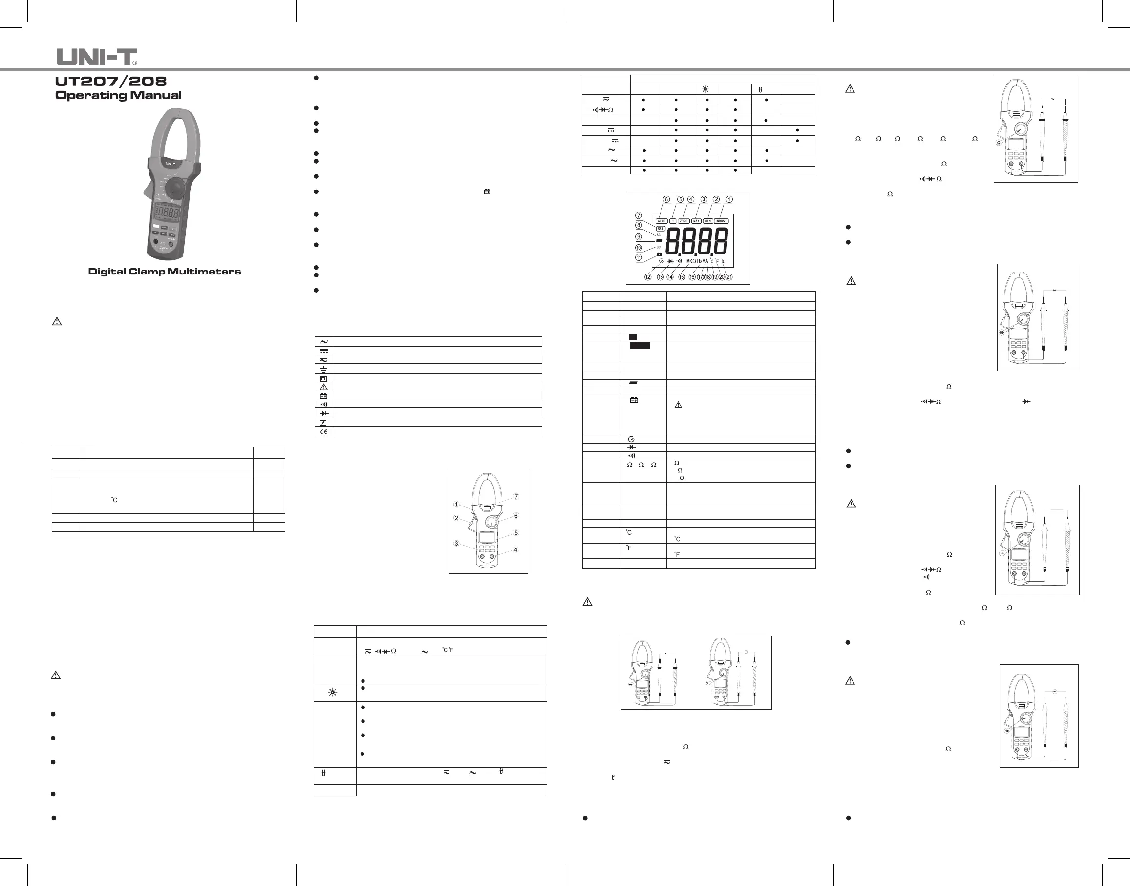
Figure 1
The Meter Structure (See Figure 1)
Hand Guards: to protect user’s hand
fromtouching the dangerous area.
Trigger: press the lever to open the
transformerjaws.Whenthepressure
ontheleverisreleased,thejawswill
close.
Functional Buttons
Input Terminals
LCD Display
Rotary Switch
Transformer Jaw: designedto pick up
the ACandDCcurrent flowing through
theconductor.It could transfercurrent
tovoltage. Thetestedconductormust
verticallygothroughtheJawcenter.
1.
2.
3.
4.
5.
6.
7.
PressSELECT button to select the alternate functions including
V
,
,%Hz,A
and
(UT208 only).
Starts recording of maximum and minimum values.
Pressto step the display through high(MAX)andlow(MIN)readings
at any mode.
Press and hold for one second to exit MAX/MIN mode.
Press to turn on the backlight, repress to turn it off,otherwise
it will automatically off after 1 minute.
Functional Buttons
Below table indicated for information about the functional button operations.
Button Operation Performed
SELECT
MAX/MIN
PressHOLD to enter the Hold mode in any mode, the Meter
beeps.
PressHOLDagaintoexittheHoldmodetoreturntomeasurement
mode, the Meter beeps.
Turning the rotary switch or pressing SELECT button can also
exit Hold mode.
HOLD
PressHOLDbuttonfor 2 secondswhenturningontheMeter to
display full icon.
WhentheMeterisat%Hz,VandA
, press Hztomeasure
frequency and duty cycle.
Hz
ZEROPressZERO to zeroing the display before measuring DC current.
The Effectiveness of Functional Buttons
Not every functional buttons can be used on every rotary switch positions.Below
table describe on which rotary switch position the functions of buttons are available.
SELECTMAX/MIN
HOLD
Hz
ZERO
N/A
%Hz
66A
1000A
66A
1000A
N/A
N/A
N/A
N/A
N/AN/A
N/A
N/A
N/A
N/A
N/A
N/A
Rotary Switch
Positions
V
FunctionalButtons
o
C
o
F
Figure 2
Display Symbols (See Figure 2)
Number Symbol Meaning
1
2
3
4
5
6
7
8
9
10
11
INRUSH
MIN
MAX
ZERO
Indicator for Surge current
Minimum reading displayed
Maximum reading displayed
Indicator for zeroing
Data hold is active
TheMeterisintheautorangemodeinwhichthe
Meterautomaticallyselects therangewith the best
resolution.
True RMS indicator
Indicator for AC voltage or current
Indicates negative reading
Indicator for DC voltage or current
The battery is low.
Warning: To avoid false readings, which
couldleadtopossibleelectricshockor
personalinjury, replace the battery assoon as
the battery indicator appears.
H
AUTO
RMS
AC
DC
12
13
14
15
16
17
18
19
20
21
Sleep mode is on
Test of diode
The continuity buzzer is on
: Ohm. The unit of resistance.
k
:Kilohm. 1x10
3
or 1000 ohms
M
:Megohm. 1x10
6
or 1,000,000 ohms
Hz: Hertz. The unit of frequency.
KHz: Kilohertz. 1x10
3
or 1000 hertz.
MHz: Meghertz. 1x10
6
or1,000,000 hertz.
Volts. The unit of voltage.
mV: Millivolt. 1x10
-3
or 0.001 volts
Amperes (amps). The unit of current.
The unit of temperature:
:Centigrade temperature
The unit of temperature:
:Fahrenheit temperature
Duty cycle measurement
,K,M
Hz, kHz, MHz
mV, V
A
%
A. Measuring DC/AC ( See Figure 3 )
To avoid harm to you or damage to the Meter from eletric shock, do not
attempt to measure voltages higher than 600V AC/DC, although readings may
be obtained.
Red
Black
Red
Black
Measurement Operation
Figure 3
Warning
The DC Voltage ranges are: 6.6V, 66V and 600V
The AC Voltage ranges are: 6.6V, 66V and 600V
To measure DC/AC voltages, connect the Meter as follows:
Insert the red test lead into the V
Hz terminal and black test lead into the COM
terminal.
Set the rotary switch to V
.DC measurement mode and auto ranging is a
default. Press SELECT to switch to AC measurement mode.
Press
Hzbutton to measure frequency or duty cycle, but thefrequency or duty
cycle readings obtained from this range is only for reference.
Connect the test leads across with the object being measured.
The measured value shows on the display.
1.
2.
3.
4.
Note
WhenDC/ACvoltagemeasurementhasbeencompleted,disconnecttheconnection
betweenthetestingleadsandthecircuitundertestandremovetestingleads
from the input terminals.
B. Measuring Resistance (See Figure 4)
To avoiddamagetotheMeterortothedevices
under test, disconnect circuit power and
discharge all the high-voltage capacitorsbefore
measuring resistance.
The resistance ranges are:
660
, 6.6k, 66k, 660k, 6.6M and 66M
To measure resistance, connect the Meter as
follows:
InserttheredtestleadintotheV
Hzterminal
and black test lead into the COM terminal.
Set the rotary switch to
. Resistance
measurement is a default or press SELECT
to switch to
measurement mode.
1.
2.
Red
Black
Figure 4
Warning
Connect the test leads across with the object being measured.
The measured value shows on the display.
3.
Note
To obtain a more precise reading, you could removethe objects being testedfrom
the circuit during measurement.
When resistance measurement has been completed, disconnect the connection
between the testing leads and the circuit under test and remove testing leads
from the input terminals.
C. Testing Diodes (See Figure 5)
To avoid damage to the Meterortothedevices
undertest,disconnectcircuitpowerand
discharge allthe high-voltage capacitors before
testing diodes.
Usethediodetesttocheckdiodes,transistors,and
othersemiconductordevices.Thediodetestsends
a current through the semicondutor junction, then
measurethevoltagedropacrossthejunction.A
goodsiliconjunctiondropsbetween0.5Vand0.8V.
To test the diode out of a circuit, connect the Meter
as follows:
Figure 5
Warning
Red
Black
Insert the red test lead into the VHz terminal and black test lead into the COM
terminal.
Set the rotary switch to
. Press SELECT to switch to measurement
mode.
For forward voltage drop readings on any semiconductor component, place the
red test lead on the component’s anode and place the black test lead on the
component’s cathode.
1.
2.
3.
Note
To obtain a more precise reading, you could remove the objectsbeing testedfrom
the circuit during measurement.
Whendiodetestinghasbeencompleted,disconnecttheconnectionbetweenthe
testing leads and the circuit under test and remove testing leads from the input
terminals.
D. Testing for Continuity (See Figure 6)
To avoid damag to the Meterortothedevices
undertest,disconnectcircuitpowerand
discharge allthe high-voltage capacitors before
measuring continuity.
To test for continuity, connect the Meter as follows:
Insert the red test lead into the V
Hz terminal
and the black test lead into the COM terminal.
Set the rotary switch to
and press
SELECTbuttontoselect
measurement mode.
The buzzer sounds if the resistance of a circuit
under test is less than 30
.
The buzzer may or may not sound if the
resistance of a circuit under test is between 30 to 100 .
The buzzer does not sound if the resistance of
1.
2.
3.
RedBlack
Warning
Figure 6
a circuit under test is higher than 100
.
Note
Whencontinuitytestinghasbeencompleted,disconnecttheconnectionbetween
the testingleads and the circuit under test and remove testing leads from the
input terminals.
E. Measuring Frequency (See Figure 7)
To avoid harm to you or damage to the Meter
fromeletricshock,donotattempttomeasure
voltageshigherthan600VAC/DC,although
readings may be obtained.
The frequency ranges are:
660Hz, 6.6kHz, 66kHz, 660kHz, 6.6MHzand66MHz.
To measurefrequency, connect theMeterasfollows:
Insert the red test lead into the V
Hz terminal
and the black test lead into the COM terminal.
Set the rotary switch to %Hz. Frequency
measurement mode is a default or press SELECT
to switch to Hzmeasurement mode.
Connect the test leads across with the object being measured.
1.
2.
3.
Red
Black
Figure 7
Warning
Note
When frequency measurement has been completed, disconnect the connection
between the testing leads and the circuit under test, and remove the testing leads
away from the input terminals of the Meter.
The measured value shows on the display.
Product specificaties
| Merk: | Uni-T |
| Categorie: | Meetapparatuur |
| Model: | UT208 |
Heb je hulp nodig?
Als je hulp nodig hebt met Uni-T UT208 stel dan hieronder een vraag en andere gebruikers zullen je antwoorden
Handleiding Meetapparatuur Uni-T

10 Augustus 2025
10 Augustus 2025
9 Juni 2025
1 Mei 2025
12 April 2025
5 April 2025
3 April 2025
3 April 2025
3 April 2025
3 April 2025
Handleiding Meetapparatuur
Nieuwste handleidingen voor Meetapparatuur
21 Januari 2026
21 Januari 2026
21 Januari 2026
20 Januari 2026
20 Januari 2026
20 Januari 2026
20 Januari 2026
20 Januari 2026
20 Januari 2026
19 Januari 2026