TDE Instruments Digalox DPM72-MPN Handleiding
TDE Instruments
Meetapparatuur
Digalox DPM72-MPN
Bekijk gratis de handleiding van TDE Instruments Digalox DPM72-MPN (8 pagina’s), behorend tot de categorie Meetapparatuur. Deze gids werd als nuttig beoordeeld door 64 mensen en kreeg gemiddeld 4.2 sterren uit 32.5 reviews. Heb je een vraag over TDE Instruments Digalox DPM72-MPN of wil je andere gebruikers van dit product iets vragen? Stel een vraag
Pagina 1/8

Digalox DPM72-MPN+
Instruction manual (Rev-2020-09)
Graphical panel meter for 500V/333mV AC/DC with RGB multi display
Package contents: Panel meter Digalox DPM72-MPN
+, mounting bracket,
5 jumpers, 2 instruction manuals (EN + DE)
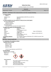
1. Safety instructions
•Read instruction manual carefully before operating the device! Keep for later
reference.
•Mounting and installation must be carried out by suitably qualified and competent
persons only.
•WARNING: The measurement inputs of the device can carry life-threatening
voltages!
•When working on the device hazardous voltages must not be connected to
the device! The terminals J1-J12 are not isolated from the measuring
circuit.
•The device must not be used as the only protective device or protective
shutdown.
•The device is not intended to protect persons or facilities against harm. Specific
devices must be used to guarantee safety (protection relays, cut-off switches,
etc.).
•When connecting switches to the terminals J1-J6, only switches must be used
whose isolation voltage is at least twice the maximum occurring measurement
voltage. For example, when measuring 250;V AC switches must be isolated for at
least 500;V.
•Do not open the housing!
•Do not use the device in the presence of explosive or flammable substances!
•All cables carrying hazardous voltages must be secured with external separators.
2. Meaning of symbols
General warning sign
(Attention, observe the documentation!)
Warning of an electrical hazard
----- ----- 1 / 8

3. Intended use
•Measurement of current, voltage, power and frequency in the specified measuring
ranges.
•Indoor use non condensing, non corrosive.
•Panel mounting.
•In operation, supply the device preferably via screw terminals with 12 to 24;V
AC/DC. If the device is supplied via USB in operation, USB supply voltage must
be at least 5;V.
•Failure to comply with these instructions will void all guarantee and warranty.
4. Description
The multi display with RGB backlight is able to display up to four parameters
simultaneously. Thresholds can be associated with individual warning backlight
colours. A variety of measurement modes (volt AC/DC, ampere AC/DC via external
shunt, frequency, power, cos phi) are supported. The unit can be switched between
measurement modes via an external switch. Minimum and maximum values of up to
four parameters are recorded and can be displayed optionally using an external
switch. Measured values of one parameter are recorded over a time span of 36
seconds up to 14 days. The time base as well as the display of the measuring
history can be activated by an external switch. The measured values remain stored
as long as the device is supplied with voltage.
The following parameters can be adjusted using the configuration software “Digalox
Manager”: scale endpoint, scale caption, display style (pointer, tachometer, bar
graph, and more), splash image, backlight colour, thresholds for alarm output,
threshold warning colour (light, blink), hysteresis, and more. Recorded
measurement values can be read and a continuous transmission of up to four
measurement values can be enabled. Using the software, values can be viewed and
exported as CSV file. Depending on the model, measured values can be transmitted
via USB, XBEE radio technology or RS485 Modbus interface. In addition, the
devices feature a counting function with data retention. This enables operating-
hours-counters or time-counters for exceeding and falling below threshold values, as
well as ampere-hour and energy meters.
Visit to download the software “Digalox Manager”.www.digalox.com
----- ----- 2 / 8

5. Product overview
3
5
4
2
1
2
6
Front
1 Unit or free text
2 Threshold values
3 Upper scale caption
4 Graphical measurement display
5 Digital measurement value
6 Lower scale caption
USB
Digalox DPM72-MPN+
www.digalox.com
Made in Germany
Outputs max.
30 V
50 mA
–
Supply
12 - 24 V
~/
+
Mode 1
Mode 2
Mode 3
Autoscale
Min/Max
Timebase
Bus 1
Bus 2
NC
GPIO 1
G
PIO 2
NC
J1
J2
J3
J4
J5
J6
J7
J8
J9
J12
J11
J10
U2low U2high U1high U1low
Shunt 333 mV max. 500 V max.
5
4
3
2
1
Back
1 2 optocoupler switch outputs
2 Jumper pins J1–J12
for activating/switching of graphical
historic data display, min/max
display, auto-scaling, measurement
mode,...
3 Supply voltage input
4 Interface (USB / XBEE / RS485)
5 Measurement inputs
6. Mounting
Carefully insert the device into the panel
cut-out. Insert the mounting bracket from
the back and push towards the panel until
the device sits tight. Make sure the
mounting bracket is snapped into the side
of the housing. To ensure IP65 protection
(dust and water jet) when mounting in a
front panel, use optional gasket
(separately available).
----- ----- 3 / 8
Panel thickness: max. 6 mm
Press mounting
bracket
Product specificaties
| Merk: | TDE Instruments |
| Categorie: | Meetapparatuur |
| Model: | Digalox DPM72-MPN |
Heb je hulp nodig?
Als je hulp nodig hebt met TDE Instruments Digalox DPM72-MPN stel dan hieronder een vraag en andere gebruikers zullen je antwoorden
Handleiding Meetapparatuur TDE Instruments

7 Juli 2023

6 Juli 2023

3 Juli 2023

2 Juli 2023

1 Juli 2023

30 Juni 2023

27 Juni 2023

26 Juni 2023
Handleiding Meetapparatuur
- KS Tools
- Victron Energy
- VirtuFit
- GlowShift
- Honeywell
- Amprobe
- RK Technology
- PQ Plus
- Benning
- Corentium
- Oregon Scientific
- Rossmax
- Testboy
- Metrel
- Techno Line
Nieuwste handleidingen voor Meetapparatuur
29 Juli 2025
29 Juli 2025
29 Juli 2025
29 Juli 2025
29 Juli 2025
29 Juli 2025
28 Juli 2025
28 Juli 2025
28 Juli 2025
28 Juli 2025