TCW Technologies SS-12v Handleiding
Bekijk gratis de handleiding van TCW Technologies SS-12v (8 pagina’s), behorend tot de categorie Niet gecategoriseerd. Deze gids werd als nuttig beoordeeld door 16 mensen en kreeg gemiddeld 4.5 sterren uit 8.5 reviews. Heb je een vraag over TCW Technologies SS-12v of wil je andere gebruikers van dit product iets vragen? Stel een vraag
Pagina 1/8

1
SmartStart
Model: SS-12v
SmartStart is an electronic control module for the engine starter system on
aircraft. SmartStart improves the safety and security of push-button or key-
switch starting systems by providing an interlocked and time limited operation of
the engine starter. SmartStart controls standard aviation starter contactors and
provides simple integration of control stick switch or panel mounted start
switches. SmartStart includes inputs for interlock and arming switches and
provides a 1 minute timer for activating the starter contactor. The SmartStart
system helps avoid unintentional activation of the engine starting system.
SS-12v is not TSO’d and must only be used in aircraft certified in the
Experimental category.
SS-12v must be installed using the current aircraft standards and
practices. Refer to AC 43.13-2A/1B. The installer/builder is solely responsible
for determining the suitability of the installation and use of this product.

2
Important Notes:
1) SmartStart has an optional Interlock Switch input that may be used to
enable/disable the start contactor. Door/canopy switches may be used to
ensure the engine cannot be started until the door/canopy is properly closed.
This input is a closure to ground to ENABLE the system.
2) It is recommended that the Arming Switch be hidden from view to improve
theft resistance of the aircraft.
3) If using a traditional aircraft keyed mag/start switch and an optional interlock
switch is used, then the terminal marked “Bat” on the key switch is connected to
pin 4, “armed power” on SmartStart.
4) Two wiring diagrams are provided, one with and one without the use of an
interlock switch.
5) All switches used with SmartStart are of the momentary type and need no
particular current rating. The switching of the start contactor is done
electronically with no moving parts and includes fly-back diode protection for the
start contactor.
6) An optional “Armed LED” indicator may be driven from the SmartStart module.
The maximum current on this pin is 50 mA. Do not use with incandescent
indicator lamps. If this feature is unused, leave this pin un-populated in the
connector.
7) An optional Airspeed Switch, model ASW-2, may be connected in parallel with
the arming switch. The use of the airspeed switch will allow in flight restarting
without the need to press the arming switch. When the aircraft is above the
airspeed switch set point (factory calibrated at 40 knots) the arming circuit is
continuously made thereby ensuring the start switch is always active in flight.
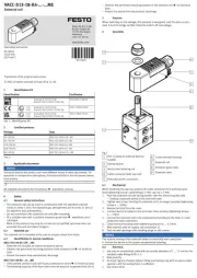
Installation instructions:
1) Select an installation diagram that matches the required installation. Diagrams
are provided for installations with and without an interlock switch connection.
Wire aircraft harness per appropriate diagram.
2) Provide power to the SmartStart module through a 5 amp fuse or breaker.
3) The SmartStart module uses a standard 9 pin D-sub connector with the male
pins on the module. Terminate the harness wires in a mating female D-sub
connector.
4) If desired, mount the “Armed LED” on the instrument panel.

3
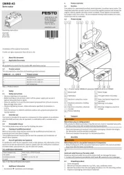
5) Mount the SmartStart module in the aircraft using the mounting tabs provided.
DO NOT mount the module in the firewall forward area.
6) If using the optionally ASW-2 airspeed switch, mount the airspeed switch via
the mounting tabs and connect the static and pitot lines to the marked ports.
The barbed fittings are sized for ¼” OD pitot and static line with a nominal ID of
3/16”. Connect the two terminals of the ASW-2 switch in parallel with the two
terminals of the arming switch.
Product operation:
If using a system that includes an interlock switch, ensure the switch is
closed. When prepared to start the aircraft engine, momentarily press the
armed switch. The activation of the arming swtich initiates a 1 minute timer,
during the 1 minute time interval closure of the Start Switch will engage the start
contactor. During the 1 minute timer interval the “Armed LED” will be
illuminated, providing feedback to the pilot that the start system is active. If the
system is installed with an optional ASW-2 airspeed switch, then the starter
system will always be armed when the aircraft is above the airspeed set-point.
TCW Technologies, LLC.
2955 Main Road East
Emmaus, PA 18049
610-928-3420
www.tcwtech.com
email: support@tcwtech.com
Product specificaties
| Merk: | TCW Technologies |
| Categorie: | Niet gecategoriseerd |
| Model: | SS-12v |
Heb je hulp nodig?
Als je hulp nodig hebt met TCW Technologies SS-12v stel dan hieronder een vraag en andere gebruikers zullen je antwoorden
Handleiding Niet gecategoriseerd TCW Technologies

5 Maart 2024

28 Februari 2024
Handleiding Niet gecategoriseerd
- Black Line
- SIGHILL
- GoGEN
- Dash
- Toa
- Koenic
- Hamlet
- InLine
- Gymrex
- Bar Fly
- Umarex
- Kwikset
- Hammond
- Selleys
- Cres Cor
Nieuwste handleidingen voor Niet gecategoriseerd

2 Augustus 2025
2 Augustus 2025
2 Augustus 2025
2 Augustus 2025
2 Augustus 2025
1 Augustus 2025

1 Augustus 2025

1 Augustus 2025
1 Augustus 2025
1 Augustus 2025