Tamron A022 Handleiding
Bekijk gratis de handleiding van Tamron A022 (4 pagina’s), behorend tot de categorie Lens. Deze gids werd als nuttig beoordeeld door 51 mensen en kreeg gemiddeld 4.0 sterren uit 5 reviews. Heb je een vraag over Tamron A022 of wil je andere gebruikers van dit product iets vragen? Stel een vraag
Pagina 1/4
TLM-A022-T/T-1607
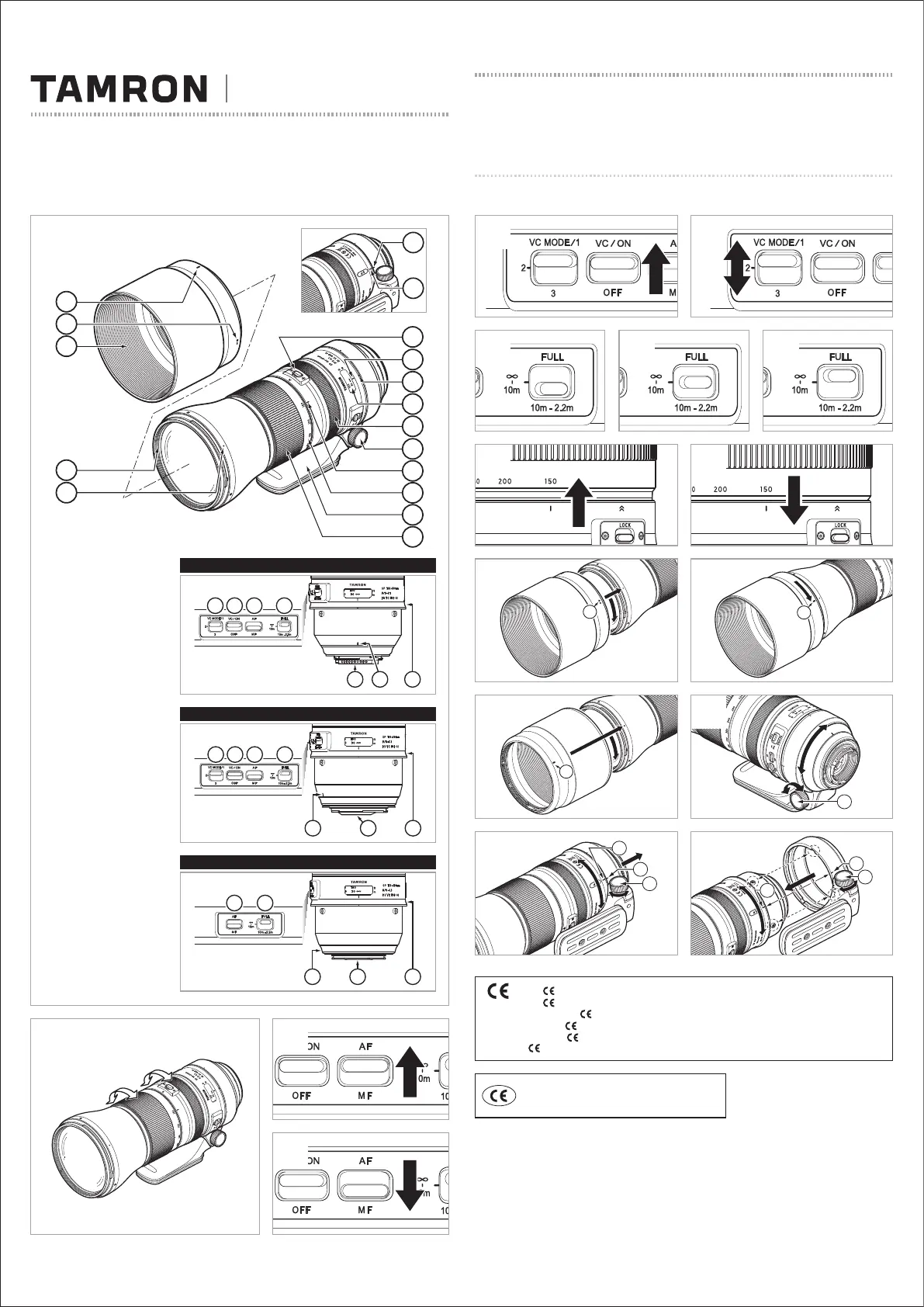
SP150-600mm F/5-6.3
Di VC USD G2
(
for Nikon, Canon
)
SP150-600mm F/5-6.3
Di USD G2
(
for Sony
*
Models without the VC
)
Model:
A022
Owner’s manual
* The Marking is a directive conformity mark of the European Community (EC).
* Das -Zeichen entspricht der EC Norm.
* La marquage est un marquage de conformité à la direcive CEE (CE).
* La marca es marca de conformidad segun directiva de la Comunidad Europea (CE).
* Il marchio attesta la conformita alla directtiva della Comunità Europea (CEE).
* 标志表示符合欧州共同体(EC)指标
The EEC Conformity Report applies to the Council
Directive 2014/30/EU, 2011/65/EU and is used by
Tamron Co., Ltd., manufacturer of this product.
16
14
15
16
14
15
14
2
3
3
Canon
Sony
Nikon
3
2
1
7
8
4
5
12
6
9
13
14
10
11
23
16
15
20211819
1522
17
20211819
1522
17
2019
1517
22
Product specificaties
| Merk: | Tamron |
| Categorie: | Lens |
| Model: | A022 |
| Kleur van het product: | Zwart |
| Vorm: | Rond |
| Materiaal: | Kunststof |
| Totale hoogte: | 600 mm |
| Compatibele lensdiameter: | - mm |
| Totale breedte: | 150 mm |
Heb je hulp nodig?
Als je hulp nodig hebt met Tamron A022 stel dan hieronder een vraag en andere gebruikers zullen je antwoorden
Handleiding Lens Tamron

6 December 2025
1 September 2025
1 September 2025
5 Augustus 2025
10 Juni 2025
2 April 2025
25 November 2024
16 November 2024
16 November 2024
16 November 2024
Handleiding Lens
Nieuwste handleidingen voor Lens
6 Maart 2026
6 Maart 2026
5 Februari 2026
28 Januari 2026
27 Januari 2026
17 Januari 2026
7 Januari 2026
6 Januari 2026
5 Januari 2026
1 Januari 2026