Sony SNC-VB642D Handleiding
Sony Bewakingscamera SNC-VB642D
Bekijk gratis de handleiding van Sony SNC-VB642D (2 pagina’s), behorend tot de categorie Bewakingscamera. Deze gids werd als nuttig beoordeeld door 265 mensen en kreeg gemiddeld 4.7 sterren uit 9 reviews. Heb je een vraag over Sony SNC-VB642D of wil je andere gebruikers van dit product iets vragen? Stel een vraag
Pagina 1/2
A
9
10
11
12
6
7
8
B
9
C
D
85.7 (3
3
/
8
)
Hole for connecting
cables ø40 (1
5
/
8
)
Horizontal maker
Hole for installing
the stand
Unit: mm (inches)
83.7 (3
3
/
10
)
Vertical marker
83.7 (3
3
/
10
)
85.7 (3
3
/
8
)
E
Ceiling
Wire rope
(supplied)
Camera unit mounting screw
(commercially-available) (4)
F
1
Liner
Twice
2
2-a LAN cable
Overlap at least
half of its width
Tab
10 (
1
/
2
)10 (
1
/
2
)
2-b SP terminal / MIC terminal / I/O (Input/Output) cable / BNC
cable
10 (
1
/
2
)10 (
1
/
2
)
10 (
1
/
2
)
Overlap at least
half of its width
SNC-VB642DSNC-EB642R
Overlap at least
half of its width
2-c Power input cable
SNC-VB642DSNC-EB642R
30 (1
1
/
4
)
Heat shrinkable tubeHeat shrinkable tube
Wrap this part
two-fold
Wrap this part
two-fold
Overlap at least
half of its width
Overlap at least
half of its width
4-696-254-11(1)
© 2017 Sony Corporation
Network Camera
SNC-VB642D/EB642R
Installation Manual
Before operating the unit, please read this manual thoroughly and
retain it for future reference.
About the Manuals
Safety Regulations (included)
The Safety Regulations describes notes for the secure usage of camera. Be sure
to read it.
Installation Manual (this document)
Describes the names and functions of parts and controls of the Network Camera,
gives connection examples and explains how to set up the camera. Be sure to
read the Installation Manual before operating.
The illustration of SNC-VB642D is used for example purpose.
Electronic Instruction Manual (Web)
How to control the camera via a web browser ˎ
How to setup the camera ˎ
Operate the camera referring to the guide above after having installed and
connected the camera properly based on the Installation Manual.
Assigning the IP address
1Download the installer for “SNC toolbox” to a folder from the download
site.
2Install the SNC toolbox.
Unzip the ZIP file of the downloaded installer.
Double-click “SncToolbox_Setup.exe.” For details on installing and use refer to
the Application Guide.
3Assign an IP address.
Assign an IP address using the installed SNC toolbox. For details, see “Using
SNC toolbox” – “Assign an IP address” in the Application Guide.
Tip
SNC toolbox stands for Sony Network Camera toolbox.
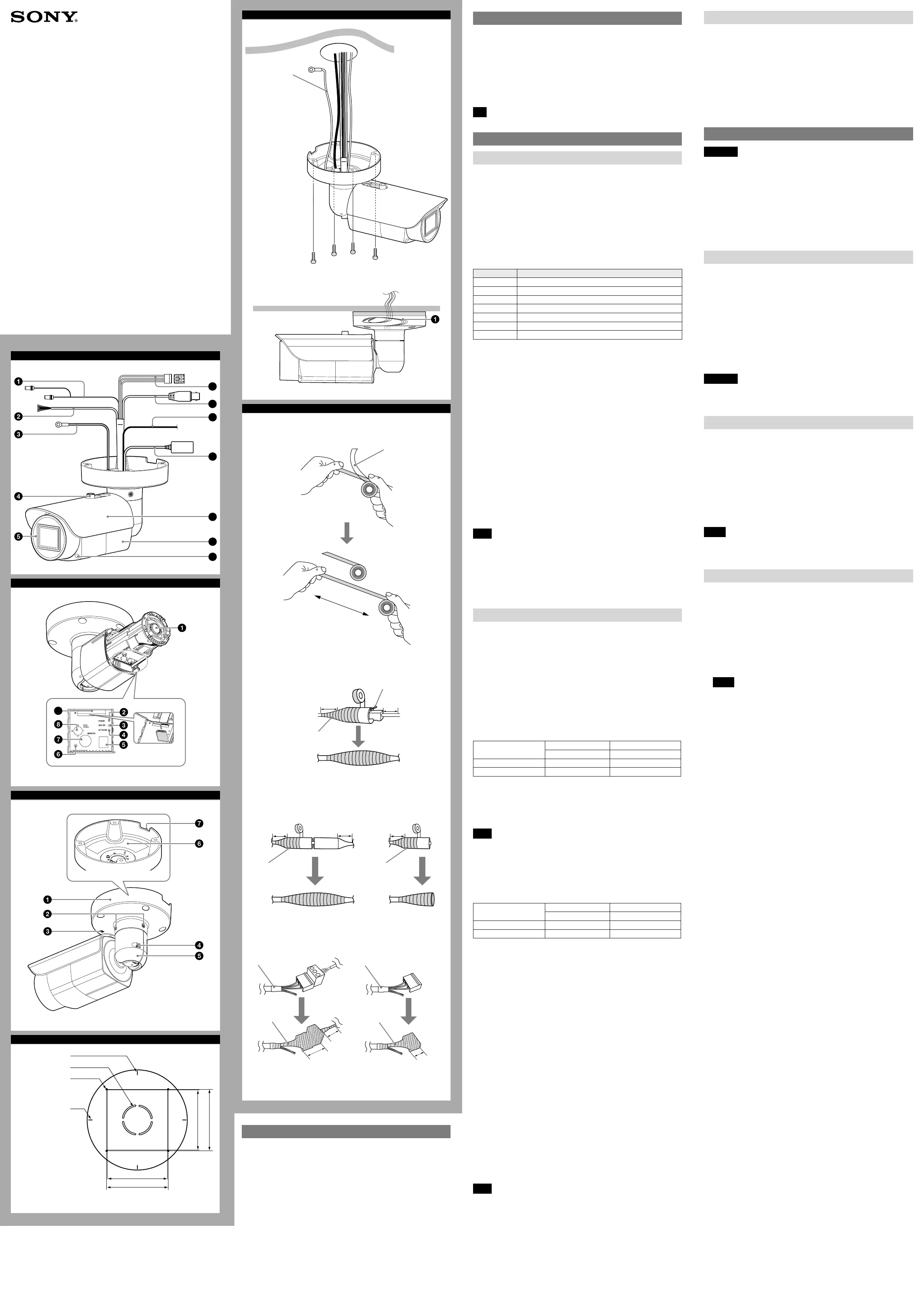
Location and Function of Part
Front
Audio cable
The connector with the longer cable (SP) is used for the line output connector,
and the shorter cable (MIC) is used for the microphone/line input connector.
SP terminal (minijack, monaural) ˎ
Connect a commercially available speaker system with a built-in amplifier.
MIC terminal (minijack, monaural) ˎ
Connect a commercially available microphone. This jack supports plugin-
power microphones (rated voltage: 2.5 V DC).
I/O (Input/Output) cable
Use for SNC-VB642D only.
This cable is provided with two sensor inputs and two alarm outputs. The wires
of the cable control the following signals.
Color of wire Name
RedSensor In 1+
WhiteSensor In 2+
BlackSensor In – (GND)
YellowAlarm Out 1+
BrownAlarm Out 1–
GreenAlarm Out 2+
BlueAlarm Out 2–
For details on each function and required settings, see the User’s Guide.
For wiring, see “Connecting the I/O Cable” (P2).
Wire rope
When installing the camera on the ceiling or the wall, make sure to attach the
supplied wire rope.
Sun shield nut
Front cover
Power input cable
Use for SNC-VB642D only.
Connect this cable to a 24 V AC or 12 V DC power supply system.
You can screw an extension cable in the connector tip attached at the end of the
cable. Connect GND to the FG terminal (center of 3-pin connector). See
illustration .
BNC cable
Outputs a composite video signal.
Ground wire
Ground the camera when you install it.
LAN cable (RJ-45)
Connect this cable to a hub or computer on the 10BASE-T or 100BASE-TX
network using a commercially available network cable (category 5).
Note
Take care not to trap the cables between the camera and the ceiling or the wall. If
the cable is trapped, it may cause a fire or electric shock due to breaking.
Sun shield
The sun shield can be adjusted horizontally up to 26 mm (1
1
/8 inches), as
required.
Camera
Front cover screw (four positions)
Inside
Lens
POWER indicator (Green)
When the power is supplied to the camera, the camera starts checking the
system. If the system is normal, this indicator lights up.
HEATER indicator (Green)
The indicator lights up in green when the built-in heater is working normally.
NETWORK indicator (Green/Orange)
The indicator lights up or flashes when the camera is connected to the network.
The indicator is off when the camera is not connected to the network.
Mode setting DIP switches
DIP switch function/settings
SNC-VB642D
Switch No.
12
VIDEOPOWER
Up (ON) PALPoE+, AC, DC
Down (OFF)NTSCPoE
1 VIDEO (NTSC/PAL) switch (Initial setting: NTSC)
Switches the video output.
After setting the switch, reboot the camera unit.
2 POWER (PoE+, AC, DC/PoE) switch (Initial setting: PoE+, AC, DC)
Change according to the power you are using.
Note
When power is supplied by IEEE802.3af (PoE) equipment, if the switch is set to
PoE+, the camera will not work properly.
When the power is supplied via power supply equipment that complies with
IEEE802.3at (PoE+), an AC power adaptor, or a DC power adaptor, the heater
will not work if the switch is set to PoE. Note that if you use the camera in a low
temperature, the camera may not work.
SNC-EB642R
Switch No.
12
VIDEOHEATER
Up (ON) PALAUTO
Down (OFF)NTSCOFF
1 VIDEO (NTSC/PAL) switch (Initial setting: NTSC)
Switches the video output.
After setting the switch, reboot the camera unit.
2 HEATER (AUTO/OFF) switch (Initial setting: AUTO)
The integrated heater function will be deactivated when it is set to OFF. Be
sure to set to AUTO when you use the camera in cool environment.
Reset switch
To reset the camera to the factory default settings, hold down this switch with a
point and supply the power to the camera.
MONITOR output jack
Connect this jack to a video input connector of a video monitor. You can adjust
the camera or lens while looking at the image on the video monitor. After
adjusting the camera or lens, disconnect the cable.
ZOOM/FOCUS switch
Use this switch to adjust lens’ zoom and focus. Slide the switch lever to select the
desired function.
[W] WIDE: Zoom out
[T] TELE: Zoom in
[N] NEAR: Focus on a nearby subject
[F] FAR: Focus on a distant subject
Hold down the center of the ZOOM/FOCUS switch for a moment to focus
automatically.
SD card slot
This slot is used for optional SD memory cards.
Image data in the camera can be recorded to a memory card by inserting it into
the slot.
Gently insert an SD card in (see illustration) until it clicks into place.
This unit is only compatible with SD and SDHC memory cards.
Note
For inquiries regarding verified SD memory cards, contact your authorized Sony
dealer.
Back
Base stand
Base screw (two positions)
TOP mark
Arm screw
Arm
Rating label
Shows the name of this camera and its electric rating.
Water drain
When installing the unit on a wall, make sure this water drain is not sealed.
Installation
WARNING
If you attach the camera in the height such as the wall or the ceiling, etc.,
ˎ
entrust the installation to an experienced contractor or installer.
If you install the camera at a height, ensure that the installation location and
ˎ
its material are strong enough to withstand a weight of 15 kg (33 lb 11 oz) or
more, and then install the camera securely. If the ceiling is not strong enough,
the camera may fall and cause serious injury.
Do not pull on any cables forcefully, as a connection may become loose.
ˎ
To prevent the camera from falling, make sure to attach the supplied wire rope.
ˎ
If you attach the camera to the ceiling, check periodically, at least once a year,
ˎ
to ensure that the connection has not loosened. If conditions warrant, make
this periodic check more frequently.
Deciding the Installation Location of the Camera
After deciding the direction in which the camera will shoot, make the required hole
(ø40 mm (1
23
/
40
inches)) for the connecting cables using the supplied template.
Then decide the four mounting hole positions to install the base stand.
Mounting screws
The camera stand is provided with four ø4.5 mm (
3
/16 inches) mounting holes.
Install the camera stand on a ceiling or wall with screws through four mounting
holes: The required mounting screws differ depending on the installation
location and its material. Use commercially-available screws.
Steel wall or ceiling: Use M4 bolts and nuts.
Wooden wall or ceiling: Use M4 tapping screws. The panel thickness must be
15 mm (
5
/8 inches) or more.
Concrete wall: Use anchors, bolts and plugs suitable for concrete walls.
Junction box: Use screws to match the holes on the junction box.
WARNING
The required mounting screws differ depending on the installation location and
its material. If you do not secure the camera with the appropriate mounting
screws, the camera may fall off.
Installing the Camera
1
Pass the cables through the hole for connecting cables made at the
installing surface.
2Fix the wire rope to the wall or ceiling.
3Install the camera on the wall or ceiling.
The remaining cable can be incorporated in the space between the base
stand and the mounting surface. (
-
)
Insert the four screws in the screw holes on the camera stand, and then
tighten the screws to attach the camera.
When installing the camera on the wall, be sure the TOP mark on the camera
stand is at the top.
Refer to “Mounting screws” in section D for screw to be used.
Notes
If you install the camera unit on a ceiling, take adequate waterproofing ˎ
measures to prevent water seepage into the stand.
When installing the unit on a wall, make sure the water drain is not sealed. ˎ
Notes on waterproofing of cable connection area
Despite the fact that this unit is rated IP66, the cables and/or the connectors
join to the outside are not waterproof. To prevent water ingress from the cables
and/or the connectors, waterproof them with the supplied waterproof tape as
follows. Otherwise, there may be a risk of water entering through the cables
and/or the connectors and shorting the unit or the connectors.
1Connect all the required cables and the ground wire.
2To obtain optimal waterproofing, tear off the liner before wrapping,
then stretch the tape to twice its original length. (
-1)
If it is not fully stretched, the waterproofing function of the tape can not be
achieved.
3Overlap the tape at least half of its width when wrapping. (-2)
Notes
Do not press the network cable tab down when wrapping it.
ˎ
When you wrap the power input cable, start from the heat shrinkable tube.
ˎ
Make sure at least 30 mm (1
1
/4 inches) of the wire part that is connected to
the power supply equipment is wrapped. (2-c)
Since the connector of the power input cable has gaps, wrap the connector
ˎ
part two-fold.
Make sure at least 10 mm (
ˎ
1
/2 inches) of the wire part (excluding the power
input cable) is wrapped.
Make sure there is no unwrapped part or damage on the tape.
ˎ
4After wrapping, squeeze the tape with your fingers at the overlapping
parts so that layers are airtight and fully adhered.
Unit: mm (inches)
Product specificaties
| Merk: | Sony |
| Categorie: | Bewakingscamera |
| Model: | SNC-VB642D |
| Kleur van het product: | Black, White |
| Gewicht: | 1620 g |
| Breedte: | 93 mm |
| Diepte: | 93 mm |
| Hoogte: | 180.9 mm |
| Soort: | IP-beveiligingscamera |
| Gebruikershandleiding: | Ja |
| Internationale veiligheidscode (IP): | IP66 |
| Maximale capaciteit van de geheugenkaart: | 256 GB |
| Ondersteund audioformaat: | AAC |
| Stemcodecs: | G.711, G.726 |
| Vormfactor: | Rond |
| Ondersteuning voor plaatsing: | Buiten |
| Connectiviteitstechnologie: | Bedraad |
| Ethernet LAN: | Ja |
| Montagewijze: | Plafond |
| Maximum resolutie: | 1920 x 1080 Pixels |
| Videocompressieformaten: | H.264 |
| Type stroombron: | Power over Ethernet (PoE) |
| Minimale belichting: | 0.006 Lux |
| Aantal cameras: | 1 |
| Geïntegreerde geheugenkaartlezer: | Ja |
| Compatibele geheugenkaarten: | SD |
| Nachtvisie: | Ja |
| LED-type: | IR |
| Infrarood wavelength: | 850 nm |
| Zoomcapaciteit: | Ja |
| Microfoon, line-in ingang: | Ja |
| Aantal Ethernet LAN (RJ-45)-poorten: | 1 |
| Brandpuntbereik: | 3 - 9 mm |
| Vermogensverbruik (max): | 21 W |
| Certificering: | UL2044, IEC60950-1, VCCI, FCC, IC, EN55032, EN55024, EN50130-4, AS/NZS CISPR32, KC, EMC-TR |
| Formaat analoog signaal: | NTSC, PAL |
| Volledige HD: | Ja |
| Omvang optische sensor: | 1/2.8 " |
| Beeldstabilisator: | Ja |
| Type beeldsensor: | CMOS |
| Digitale zoom: | 4 x |
| Optische zoom: | 3 x |
| Camera sluitertijd: | 1 - 1/10000 s |
| Witbalans: | ATW, Fluorescent, Indoor, Manual, Mercury lamp, One push, Outdoor, Sodium lamp |
| Ondersteunde grafische resoluties: | 352 x 288,640 x 360,640 x 480 (VGA),704 x 576,720 x 480,720 x 576,1024 x 576 (WSVGA),1280 x 720 (HD 720),1920 x 1080 (HD 1080) |
| Webbrowser: | Ja |
| Ruisonderdrukking: | Ja |
| Bekabelingstechnologie: | 10/100Base-T(X) |
| Netwerkstandaard: | IEEE 802.1x |
| Ondersteunt Windows: | Windows 10, Windows 7, Windows 8.1 |
| Aantal gebruikers: | 20 gebruiker(s) |
| Temperatuur bij opslag: | -20 - 60 °C |
| Veiligheidsfunties: | Vandaalbestendig |
| Maximaal 30 frames per seconde: | 60 fps |
| Ondersteunde netwerkprotocollen: | IPv4, TCP, UDP, ARP, ICMP, IGMP, HTTP, DHCP, DNS, NTP, RTP/RTCP, RTSP over TCP, SMTP over HTTP, IPv6, HTTPS, FTP (client), SNMP (v1, v2c, v3), SSL |
| Luchtvochtigheid bij opslag: | 20 - 80 procent |
| Frequentiebereik: | 16000 - 48000 Hz |
| Progressive scan: | Ja |
| Ethernet interface type: | Fast Ethernet |
| Signaal/ruis-verhouding: | 50 dB |
| Ondersteunde talen: | ARA, CHI (SIMPL), CHI (TR), DEU, ENG, ESP, FRE, HIN, ITA, JPN, KOR, POL, POR, RUS, THA, TUR |
| Quality of Service (QoS): | Ja |
| Power over Ethernet (PoE): | Ja |
| Dichtstbijzijnde focus afstand: | 0.3 m |
| PTZ control: | Ja |
| Minimale processor: | Intel Corei7 2.8 GHz |
| Dag/nacht modus: | Ja |
| Maximum aperture number: | 2.1 |
| Minimum aperture number: | 1.2 |
| Methode voor streaming: | Multicast |
| BNC output ports: | 1 |
| Weerbestendig: | Ja |
| Nachtkijker afstand: | 100 m |
| Alarm ingang/uitgang: | Ja |
| Lens type: | Varifocaal |
| Aantal talen: | 17 |
| Bitratecontrole: | Constant Bit Rate (CBR), Variable Bit Rate (VBR) |
| Stroomverbruik (voeding via Ethernet (PoE)): | 17 W |
| Bitrate: | 64 Kbps - 32 Mbps |
| AC-ingangsspanning: | 24 V |
| Bedrijfstemperatuur (T-T): | -40 - 60 °C |
| Relatieve vochtigheid in bedrijf (V-V): | 20 - 90 procent |
| Privézone maskeren: | Ja |
| Systeemfuncties intelligente videobewaking (IVS): | Abandoned object, Face detection, Missing object |
| Kijkhoek lens, horizontaal: | 105.3 ° |
| Lens mount interface: | CS-aansluiting |
| Kijkhoek lens, verticaal: | 56.9 ° |
| Automatische versterking control: | Ja |
| Iris: | Ja |
| Ingebouwde verwarming: | Ja |
Heb je hulp nodig?
Als je hulp nodig hebt met Sony SNC-VB642D stel dan hieronder een vraag en andere gebruikers zullen je antwoorden
Handleiding Bewakingscamera Sony

30 Oktober 2025
3 Oktober 2025
3 Oktober 2025
7 Juli 2025
7 Juli 2025
7 Juli 2025
7 Juli 2025
7 Juli 2025
7 Juli 2025
7 Juli 2025
Handleiding Bewakingscamera
Nieuwste handleidingen voor Bewakingscamera
9 Juni 2026
8 Juni 2026
8 Juni 2026
8 Juni 2026
8 Juni 2026
8 Juni 2026
8 Juni 2026
8 Juni 2026
8 Juni 2026
8 Juni 2026