Simrad Recon UI Board Handleiding
Simrad Niet gecategoriseerd Recon UI Board
Bekijk gratis de handleiding van Simrad Recon UI Board (8 pagina’s), behorend tot de categorie Niet gecategoriseerd. Deze gids werd als nuttig beoordeeld door 30 mensen en kreeg gemiddeld 5.0 sterren uit 5 reviews. Heb je een vraag over Simrad Recon UI Board of wil je andere gebruikers van dit product iets vragen? Stel een vraag
Pagina 1/8
Recon
™
Mount Controller UI Board
Installation Guide: EN
Document version: 001
⚠WARNING: This product must be installed in
accordance with the instructions provided. Failure to do
so could result in personal injury, damage to your vessel
and/or poor product performance.
⚠WARNING: Performing service or maintenance
without rst disconnecting the battery can cause product
damage, personal injury, or death due to re, explosion,
electrical shock, or unexpected motor starting. Always
disconnect the battery cables from the battery before
maintaining, servicing, installing, or removing motor
components.
In the box
• 1x Recon™ mount controller UI board
• 1x upper routing bracket
• 1x lower routing bracket
• 3x cable ties
• 5x M3-0.5 x 8, flange, hex, SS screws
• 2x #6 x 3/8 pan, T15 Torx
®
, SS screws
• 3x 1/4-28 x 3/8, button, hex, SS screws
• 6x M4-0.7 x 18, socket, hex, SS screws
• 2x #6 x 3/4, pan, T15 Torx
®
, SS screws
Tools needed
• #2 Phillips bit or screwdriver
• Knife or cutters
• 2 mm Allen key
• 3 mm Allen key
• 5/32 in Allen key
• T15 Torx
®
bit or screwdriver
• Torque wrench
• Dielectric grease
Introduction
The trolling motor’s sensors, cables, and user interface
lights and keys connect to the mount controller UI board
(mount controller board) inside the trolling motor mount.
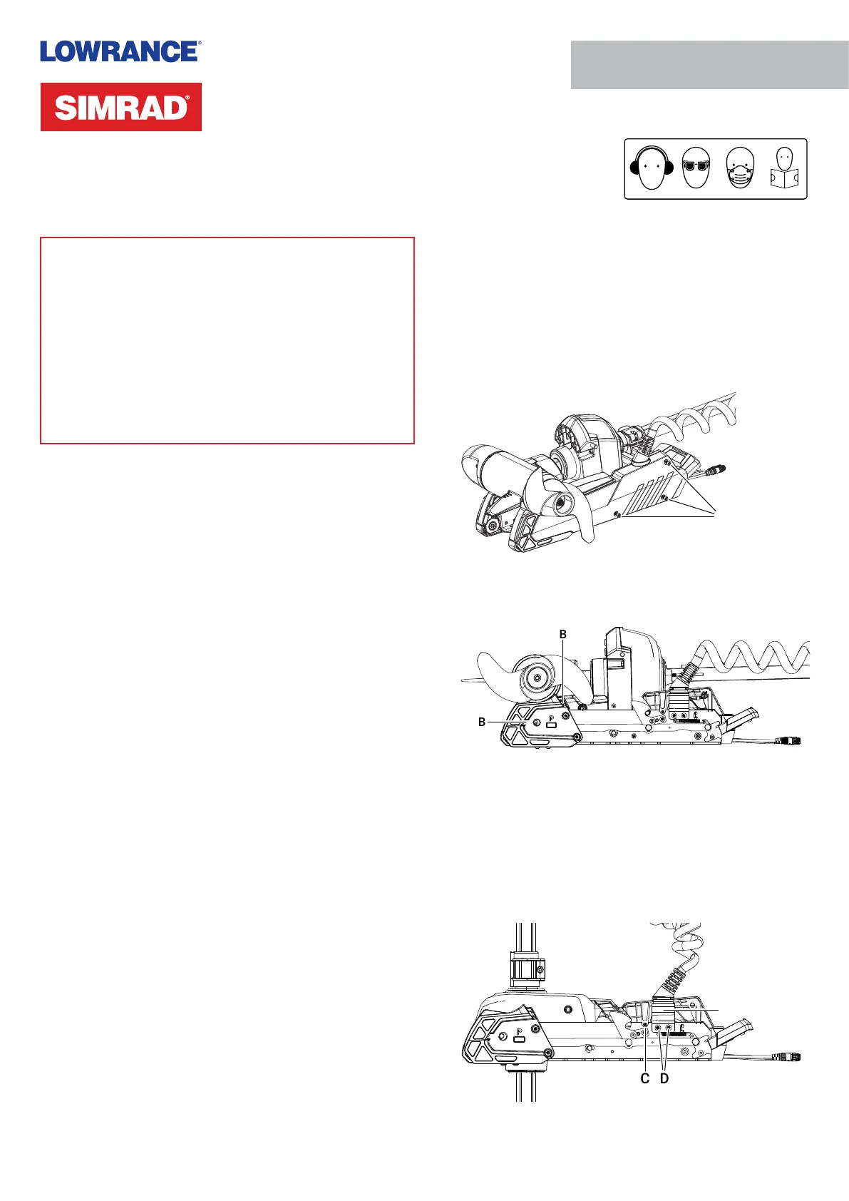
Remove side plates and mount UI cover
1 Disconnect the trolling motor power cable from the
battery (or unplug the power cable if using a plug and
receptacle).
2 While your trolling motor is stowed or deployed, use a
#2 Phillips screwdriver to loosen the side plate screws
on both sides of the mount (A).
¼Note: The screws are retained by washers.
A
3 Remove the side plates, taking care not to damage the
locating tabs as they leave their slots (B).
B
B
4 Deploy the trolling motor.
5 Use a 2 mm Allen key to remove the screw from both
sides of the UI cover (C).
6 Use a 5/32 in Allen key to loosen the two screws (D) that
secure the coil cable bracket 2–3 full rotations. These
screws have a blue thread-locking compound applied to
them. Ease the coil cable bracket (E) outward from the
mount.
C
D
E
Product specificaties
| Merk: | Simrad |
| Categorie: | Niet gecategoriseerd |
| Model: | Recon UI Board |
Heb je hulp nodig?
Als je hulp nodig hebt met Simrad Recon UI Board stel dan hieronder een vraag en andere gebruikers zullen je antwoorden
Handleiding Niet gecategoriseerd Simrad

14 Maart 2026
5 November 2025
30 Juli 2025
29 Juli 2025
29 Juli 2025
29 Juli 2025
29 Juli 2025
8 Juni 2025
7 April 2025
31 Maart 2025
Handleiding Niet gecategoriseerd
Nieuwste handleidingen voor Niet gecategoriseerd
23 Juli 2026
23 Juli 2026
23 Juli 2026
23 Juli 2026
23 Juli 2026
23 Juli 2026
23 Juli 2026
23 Juli 2026
23 Juli 2026
22 Juli 2026