Siemens ET63RBEA8E Handleiding
Bekijk gratis de handleiding van Siemens ET63RBEA8E (16 pagina’s), behorend tot de categorie Fornuis. Deze gids werd als nuttig beoordeeld door 28 mensen en kreeg gemiddeld 4.0 sterren uit 14.5 reviews. Heb je een vraag over Siemens ET63RBEA8E of wil je andere gebruikers van dit product iets vragen? Stel een vraag
Pagina 1/16

1
*9000967051* 9000967051 020726
de Montageanleitung
en Installation instructions
fr Notice d'installation
it Istruzioni d'installazione
nl Installatie-instructies
da Installationsvejledning
pt Instruções de instalação
es Instrucciones de montaje
el Οδηγίες εγκατάστασης
no Installasjonsveiledning
sv Installationsanvisningar
fi Asennusohjeet
ru Инструкция по установке
cs Pokyny kinstalaci
pl Instrukcje montażu
tr Kurulum talimatları
1
2 3
de
Sichere Montage
Beachten Sie diese Sicherheitshinweise,
wenn Sie das Gerät montieren.
¡Elektrischer Anschluss nur durch konzes-
sioniertes Fachpersonal. Bei Falschan-
schluss erlischt die Garantie.
¡Nur ein fachgerechter Einbau nach dieser
Montageanweisung garantiert einen siche-
ren Gebrauch. Bei Schäden durch nicht
fachgerechten Einbau haftet der Monteur.
Unterbau
Keine Kühlgeräte, Geschirrspüler, unbelüftete Backö-
fen und Waschmaschinen unterbauen.
¡Wenn Sie einen Modular- oder einen Kompakt-Ge-
schirrspüler der gleichen Marke unterbauen, muss
die Arbeitsplattendicke mindestens 40mm betra-
gen.

2
¡Wenn Sie einen Backofen unterbauen, muss die
Arbeitsplattendicke mindestens 20mm betragen,
in manchen Fällen auch mehr. Beachten Sie die
Hinweise in der Montageanleitung des Backofens.
¡Achten Sie darauf, dass vorstehende Teile wie z.B.
das Netzanschlussgehäuse oder das Netzan-
schlusskabel nicht mit z.B. einer Schublade kolli-
dieren.
Zwischenboden
Wenn die Kochfeldunterseite berührbar ist, muss ein
Zwischenboden montiert werden.
¡Fragen Sie im Fachhandel nach einem Zwischen-
boden als Zubehör.
¡Wenn Sie einen eigenen Zwischenboden verwen-
den, muss der Mindestabstand zum Netzan-
schluss des Geräts 10mm betragen.
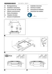
Möbel vorbereiten
Die Arbeitsplatte muss eben, waagrecht und stabil
sein.
¡Die Einbaumöbel inklusive Wandabschlussleisten
müssen mindestens 90°C hitzebeständig sein.
¡Eine Nieschenverkleidungen innerhalb des 50mm
Abstands zur Rückwand darf nicht brennbar sein
(z.B. Fliesen, Stein).
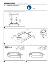
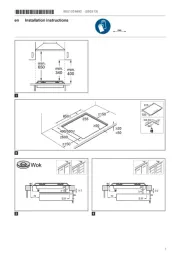
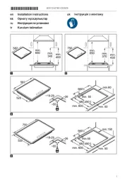
¡Die Schnittflächen hitzebeständig versiegeln, um
ein Aufquellen der Arbeitsplatte durch Feuchtigkeit
zu verhindern.
→Abb. 1
Elektrischer Anschluss
Zum Schutz das Gerät erst aus den Styroporschalen
nehmen, wenn Sie das Gerät in den Ausschnitt
drücken. Das Gerät nie hochkant auf einer Geräte-
seite abstellen.
¡Überprüfen Sie vor dem Geräteanschluss die
Hausinstallation.
¡Das Gerät entspricht der SchutzklasseI und darf
nur in Verbindung mit Schutzleiteranschluss betrie-
ben werden.
¡In der festverlegten elektrischen Installation ist ei-
ne Trennvorrichtung in den Phasen nach den Er-
richtungsbestimmungen vorzusehen.
¡Wenn auf dem Display des Geräts erscheint,
ist es falsch angeschlossen. Gerät vom Netz tren-
nen, Anschluss überprüfen.
Anschluss mit 3-adriger Leitung
Achten Sie auf eine geeignete Absicherung der
Hausinstallation.
Beachten Sie die Farbcodierung der Netzanschluss-
leitung.
¡Grün-Gelb ist der Schutzleiter .
¡Blau ist der Neutralleiter.
¡Braun ist die Phase (Außenleiter).
¡Die Leitung ist bei Bedarf durch eine mehrphasige
Anschlussleitung ersetzbar. Bei Austausch der Lei-
tung folgenden Absatz beachten.
Anschluss ohne vormontierter Leitung
Das Kochfeld nur nach Anschlussbild anschließen.
¡Die beiliegenden Kupferbrücken bei Bedarf ein-
bauen.
¡Die Netzanschlussleitung muss dem Typ H05VV-
F oder höherwertig entsprechen.
¡Der Adernquerschnitt ist entsprechend der Strom-
belastung zu bestimmen. Nicht zulässig ist ein
Querschnitt <1,5mm².
Anschluss mit vormontierter 5-adrigen Anschluss-
leitung
Nur geschultes Kundendienstpersonal darf die An-
schlussleitung austauschen.
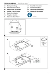
Kochfeld einsetzen
Die Anschlussleitung nicht einklemmen und nicht
über scharfe Kanten führen.
¡Bei untergebautem Backofen, die Leitung an den
hinteren Ecken des Backofens zur Anschlussdose
führen.
→Abb. 2
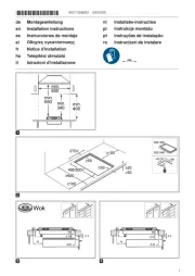
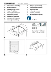
¡Das Kochfeld kann auch in einen vorhandenen
500mm tiefen Ausschnitt eingebaut werden.
¡Es muss vorn und hinten gleich weit überstehen.
→Abb. 3
Kochfeld ausbauen
1. Das Gerät spannungslos machen.
2. Das Kochfeld von unten herausdrücken.
en
Safe installation
Follow these safety instructions when in-
stalling the appliance.
¡Electrical connection must only be carried
out by licensed specialist staff. Incorrect
connection will invalidate the warranty.
¡The safe operation of this appliance can
only be guaranteed if it has been installed
to a professional standard in accordance
with these installation instructions. The in-
staller shall be liable for any damage res-
ulting from incorrect installation.
Built-under
Do not install refrigerators, dishwashers, non-ventil-
ated ovens or washing machines underneath the ap-
pliance.
¡If you fit a modular or compact dishwasher of the
same brand underneath the appliance, the work-
top must be at least 40mm thick.
¡If you fit an oven below the appliance, the worktop
must be at least 20mm thick, in certain cases
even thicker. Observe the information in the oven
installation instructions.
¡Make sure that projecting parts such as the mains
housing or the mains cable do not collide, e.g.
with a drawer.
Intermediate floor
If the underside of the hob can be touched, an inter-
mediate floor must be fitted.
¡Ask your specialist retailer for an intermediate
floor as an accessory.
¡If you use your own intermediate floor, the min-
imum distance to the mains connection of the ap-
pliance must be 10mm.
Preparing the units
The worktop must be level, horizontal and stable.
¡The fitted units, including wall finishing strips, must
be heat-resistant to at least 90°C.
¡Niche cladding within 50mm of the back wall
must not be combustible (e.g. tiles, stone).
¡Seal the cut surfaces to make them heat-resistant.
This prevents the worktop from swelling as a res-
ult of moisture.
→Fig. 1

3
Electrical connection
To protect the appliance, do not remove it from the
polystyrene trays until you press the appliance into
the cut-out. Never lay the appliance down flat on its
side.
¡Check the household wiring before connecting the
appliance.
¡The appliance fulfils the requirements of protection
classI and must only be operated in conjunction
with an earth conductor.
¡In the permanent electrical installation, a partition
must be provided in the phases in accordance
with the installation regulations.
¡If appears on the appliance's display, it has
not been connected correctly. Disconnect the ap-
pliance from the mains and check the connection.
Connecting with a 3-wire cable
Ensure that there is sufficient fuse protection for the
household wiring.
Observe the colour coding of the power cable.
¡The protective conductor is green/yellow .
¡The neutral conductor is blue.
¡The phase (external conductor) is brown.
¡If required, the cable must be replaced with a
multi-phase power cable. When replacing the
cable, observe the following paragraph.
Connecting without a pre-installed cable
Only connect the hob in accordance with the con-
nection diagram.
¡If required, install the enclosed copper bridges.
¡The power cable must correspond to
typeH05VV-F or a higher rating.
¡Use the current load to determine which wire
cross-section you require. A cross-section of
<1.5mm² is not permitted.
Connecting with a pre-installed 5-wire power cable
The power cable must only be replaced by trained
customer service personnel.
Installing the hob
Do not trap the power cable and do not route it over
sharp edges.
¡If the oven is a built-under type, route the cable
along the rear corners of the oven to the mains
socket.
→Fig. 2
¡The hob can also be installed in an existing cut-
out that has a depth of 500 mm.
¡It must protrude by the same distance at the front
and the rear.
→Fig. 3
Removing the hob
1. Disconnect the appliance from the power supply.
2. Push out the hob from below.
fr
Installation en toute
sécurité
Respectez les consignes de sécurité
lorsque vous installez cet appareil.
¡Branchement électrique uniquement par
un personnel qualifié agréé. Toute erreur
de branchement annule la garantie.
¡Seule une installation effectuée selon les
présentes recommandations de montage
garantit une utilisation en toute sécurité.
L'installateur est responsable en cas de
dommages dus à une installation incor-
recte.
Éléments installés en dessous
N'installez aucun réfrigérateur, lave-vaisselle, four
non ventilé ou lave-linge en-dessous.
¡Si vous installez en-dessous un lave-vaisselle mo-
dulaire ou compact de la même marque, l'épais-
seur du plan de travail doit être d'au moins 40
mm.
¡Si vous installez un four en-dessous, l'épaisseur
du plan de travail doit être d'au moins 20mm,
voire plus dans certains cas. Respectez les ins-
tructions de montage du four.
¡Veillez à ce que les parties saillantes, telles que le
boîtier d’alimentation ou le câble d’alimentation,
n’entrent pas en collision avec un tiroir, par
exemple.
Plancher intermédiaire
Si le dessous de la table de cuisson peut être tou-
ché, il est nécessaire de monter un plancher inter-
médiaire.
¡Des planchers intermédiaires sont en vente dans
le commerce spécialisé comme accessoire.
¡Si vous utilisez votre propre plancher intermé-
diaire, la distance minimale par rapport à la prise
secteur de l’appareil doit être de 10mm.
Préparation du meuble
Le plan de travail doit être plat, horizontal et stable.
¡Les meubles d'encastrement, y compris les
plinthes de finition murale, doivent résister à une
chaleur d'au moins 90°C.
¡Un revêtement de niche situé à moins de 50mm
de la paroi arrière doit être incombustible (par ex.
carrelages, pierre).
¡Scellez les surfaces de coupe de manière à ce
qu'elles résistent à la chaleur, afin d'éviter que
l'humidité ne fasse gonfler le plan de travail.
→Fig. 1
Branchement électrique
Pour le protéger, retirez l'appareil des coques en po-
lystyrène uniquement avant l'enfoncer dans la dé-
coupe. Ne posez jamais l'appareil à la verticale sur
un de ses côtés.
¡Avant de raccorder l'appareil, vérifiez l'installation
domestique.
¡L'appareil correspond à la classe de protection I
et doit uniquement être utilisé avec un raccorde-
ment à la terre.
¡Dans l'installation à câblage fixe, un système
coupe-circuit dans les phases est à prévoir confor-
mément aux réglementations d'installation.
¡Si apparaît sur l'affichage de l'appareil, c'est
qu'il est mal raccordé. Débranchez l'appareil du
secteur, vérifiez le branchement.
Raccordement avec un câble à 3fils
Veillez à ce que l'installation domestique soit suffi-
samment protégée par fusible.
Respectez le code couleur du câble de raccorde-
ment secteur.
¡Le conducteur de protection est vert-jaune .
¡Le conducteur neutre est bleu.
¡La phase (conducteur externe) est marron.
Product specificaties
| Merk: | Siemens |
| Categorie: | Fornuis |
| Model: | ET63RBEA8E |
| Apparaatplaatsing: | Ingebouwd |
| Soort bediening: | Touch |
| Kleur van het product: | Zwart |
| Aantal vermogenniveau's: | 17 |
| Ingebouwd display: | Ja |
| Gewicht: | 7600 g |
| Breedte: | 592 mm |
| Diepte: | 522 mm |
| Hoogte: | 45 mm |
| Snoerlengte: | 1 m |
| Kinderslot: | Ja |
| Gewicht verpakking: | 8300 g |
| Breedte verpakking: | 750 mm |
| Diepte verpakking: | 590 mm |
| Hoogte verpakking: | 100 mm |
| Soort materiaal (bovenkant): | Glaskeramiek |
| Vermogen brander/kookzone 2: | 2000 W |
| Vermogen brander/kookzone 3: | 1200 W |
| Vermogen brander/kookzone 1: | 1200 W |
| Aantal branders/kookzones: | 4 zone(s) |
| Type kookplaat: | Keramisch |
| Type brander/kookzone 1: | Klein |
| Type brander/kookzone 2: | Medium |
| Type brander/kookzone 3: | Klein |
| Aantal gaspitten: | 0 zone(s) |
| Aantal elektronische kook zones: | 4 zone(s) |
| Controle positie: | Boven voorzijde |
| Aangesloten lading (elektrisch): | 6600 W |
| Installatie compartiment breedte: | 560 mm |
| Installatie compartiment hoogte: | 45 mm |
| Aan/uitschakelaar: | Ja |
| Aangesloten lading (gas): | - W |
| Breedte kookplaat: | 59.2 cm |
| Installatie compartiment diepte (min): | 490 mm |
| Restwarmte-indicator: | Ja |
| Panherkenning: | Ja |
| Hoogte onder werkblad: | 6 mm |
| Type brander/kookzone 4: | Groot |
| Vermogen brander/kookzone 4: | 2200 W |
| Voedingsbron brander/kookzone 1: | Electrisch |
| Voedingsbron brander/kookzone 2: | Electrisch |
| Voedingsbron brander/kookzone 3: | Electrisch |
| Voedingsbron brander/kookzone 4: | Electrisch |
| Duurzaamheidscertificaten: | CE, VDE |
| Installatie compartiment diepte (max): | 500 mm |
| Positie brander/kookzone 1: | Links voor |
| Diameter brander/kookzone 1: | 145 mm |
| Positie brander/kookzone 2: | Links achter |
| Diameter brander/kookzone 2: | 180 mm |
| Positie brander/kookzone 3: | Rechts achter |
| Diameter brander/kookzone 3: | 145 mm |
| Positie brander/kookzone 4: | Rechts voor |
| Diameter brander/kookzone 4: | 210 mm |
| Kookzone 1 vorm: | Rond |
| Kookzone 2 vorm: | Rond |
| Kookzone 3 vorm: | Rond |
| Kookzone 4 vorm: | Rond |
| AC-ingangsspanning: | 220 - 240 V |
| AC-ingangsfrequentie: | 50/60 Hz |
| Type beeldscherm: | LED |
| Inbouw afzuigkap: | Nee |
Heb je hulp nodig?
Als je hulp nodig hebt met Siemens ET63RBEA8E stel dan hieronder een vraag en andere gebruikers zullen je antwoorden
Handleiding Fornuis Siemens

15 Juni 2025
15 Juni 2025
15 Juni 2025
9 Juni 2025

7 Juni 2025
6 Juni 2025
3 Juni 2025
2 Juni 2025
7 April 2025

29 Maart 2025
Handleiding Fornuis
- Lofra
- Navitel
- Roadeyes
- Coyote
- Lacunza
- ZLine
- Primo
- Unold
- Premium Levella
- InAlto
- Blaupunkt
- Brixton
- Monogram
- Oranier
- Consul
Nieuwste handleidingen voor Fornuis
30 Juli 2025
30 Juli 2025

29 Juli 2025

29 Juli 2025
29 Juli 2025
29 Juli 2025
29 Juli 2025
29 Juli 2025

29 Juli 2025
29 Juli 2025