Seitron TAS01M Handleiding
Seitron Thermostaat TAS01M
Bekijk gratis de handleiding van Seitron TAS01M (4 pagina’s), behorend tot de categorie Thermostaat. Deze gids werd als nuttig beoordeeld door 52 mensen en kreeg gemiddeld 4.0 sterren uit 6 reviews. Heb je een vraag over Seitron TAS01M of wil je andere gebruikers van dit product iets vragen? Stel een vraag
Pagina 1/4
TA S01M 0001 AN 020620A5 100512
7$6
7(50267$72(/(77521,&2$0%,(17(3(56,67(0,',5,6&$/'$0(172
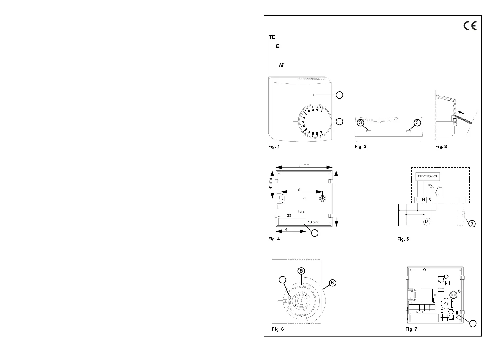
(/(&7521,&52207+(50267$7)25+($7,1*6<67(0
7+(50267$7(/(&7521,48('$0%,$1&(32856<67Ê0(6'(&+$8))$*(
7(50267$72(/(&75Ï1,&2'($0%,(17(3$5$6,67(0$6'(&$/()$&&,Ï1
)LJ
)LJ
)LJ
)LJ
4
ELECTRONICS
230V~
LN
M
LN3
NO
C
5
NC
78
SENSOR
REMOTE
)LJ
~
)LJ
3NL
8
7
654
2
3
7
6
54
)LJ
.
Cable Aperture
38 mm
10 mm
43 mm
82 mm
60 mm
41 mm
82 mm
1
Product specificaties
| Merk: | Seitron |
| Categorie: | Thermostaat |
| Model: | TAS01M |
Heb je hulp nodig?
Als je hulp nodig hebt met Seitron TAS01M stel dan hieronder een vraag en andere gebruikers zullen je antwoorden
Handleiding Thermostaat Seitron

4 Maart 2024
4 Maart 2024
4 Maart 2024
4 Maart 2024
4 Maart 2024
4 Maart 2024
4 Maart 2024
4 Maart 2024
4 Maart 2024
4 Maart 2024
Handleiding Thermostaat
Nieuwste handleidingen voor Thermostaat
14 Juli 2026
12 Juli 2026
10 Juli 2026
9 Juli 2026
8 Juli 2026
12 Juni 2026
4 Juni 2026
3 Juni 2026
3 Juni 2026
3 Juni 2026