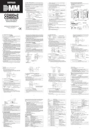
Sanwa AP33 Handleiding
Sanwa
Multimeter
AP33
Bekijk gratis de handleiding van Sanwa AP33 (2 pagina’s), behorend tot de categorie Multimeter. Deze gids werd als nuttig beoordeeld door 75 mensen en kreeg gemiddeld 5.0 sterren uit 38 reviews. Heb je een vraag over Sanwa AP33 of wil je andere gebruikers van dit product iets vragen? Stel een vraag
Pagina 1/2

− 3 −
1-4 General Handling Precautions
1. Vibration:
Do not place the tester on vehicles such as motorcycles as it is exposed to
frequent vibration that causes a tester failure.
2. Environment:
Do not store the tester for long hours in places where it is exposed to direct sunlight,
high temperature (over 60 ℃), high humidity (over 85 %) or where condensation occurs.
3. Electrification:
The tester cover has been treated by antistatic coating. Do not rub it with cloth strongly.
4. Maintenance:
When servicing the tester, wipe off dust and dirt lightly with a brush or cloth.
Do not use a solvent such as thinner and alcohol.
5. Caution:
Do not use the tester near places where strong electromagnetic waves
are generated or charged substances are present.
[2] Application and Features
2-1 Application
This is a pocket type portable analog multitester designed for measuring small-
capacity power lines.
This tester is suitable for measuring voltages and testing continuity of household
appliances and measuring voltages of electric light circuits, batteries, etc.
2-2 Features
●
A pocket size AMT with a built-in shock absorbing rubber.
[3] Panel Description
1
2
3
4
5
6
7
8
9
10
11
12
13
14
Test pins
Finger
guards
Removable
test pin covers
When not covered
8. (OFF)
9. Range selector
10. DC voltage range
11. AC voltage range
12. Meter 0-position adjuster
13. Test pins
14. Removable test pin covers
1. Protector
2. Analog display
3. 0 Ω adjuster
4. Resistance range
5. Battery test range
6. DC current renge
7. Test leads
Observe the instructions listed below in operating this equipment to
avoid a fatal accident that may result in “electric shock” and
”injuries.”
1. Do not use the tester in a power line exceeding 3.6 kVA.
2.
Pay special attention when measuring the voltage of AC 33 V(46.7peak),
DC 70 V or more to avoid injury.
3.
Do not input signals that exceed the maximum rated input value.
4. Do not measure lines (such as motor lines) where inductive
voltages and surge voltages will occur as they may exceed the
maximum overload input value.
5. Do not operate the meter when the main body or test lead is
damaged or broken.
6. Do not use the tester with its case removed.
7. Do not change function during measurement.
8. Confirm the function every time when making measurement.
9. Do not use the tester with wet hand.
10. Be sure to use the designated test leads.
11. Do not attempt repair or modification, except for replacement of
the built-in battery.
12.
Be sure to carry out startup checks and inspections at least once a year.
13. This tester is for indoor use.
− 2 −
●WARNING
1-2 Warning Instructions for Safe Use
1-3 Maximum Overload Protective Input
※1 (Tested by applying load 9 times for 0.5 sec. and once for 5 sec. every about
one minute.)
Function(Range) Input
Terminal *1 Max. Overload Protective Input
DCV 500 V AC DC 550 V or peak max770 V・
250 V/50 V AC DC 500 V or peak max700 V・
10 V AC DC 250 V or peak max350 V・
ACV 500 V AC DC 550 V or peak max770 V・
250 V/50 V AC DC 500 V or peak max700 V・
DCA 250 mA AC DC 10 V or peak max14 V・
25 mA AC DC 3 V or peak max4.2 V・
Ω ×1 k AC DC 135 V or peak max189 V・
× ・10 AC DC 15 V or peak max21 V
BATT. 9 V/1.5 V AC DC 35 V or peak max49 V・
+ −,
− 5 −
4-4 DC Current (DC mA) Measurement
①Turn the range selector to a
desired range of “DC mA”.
②Turn off the power switch of a
circuit to measure to isolate the
object to be measured.
③Connect the black test pin to the
negative side of the circuit to
measure and the red test pin to
the positive side.
WARNING: Connect the tester in series with the circuit.
④Read the measured value on the mA scale (black).
WARNING: Never apply voltage.
B
a
t
t
e
r
y
4-5 Resistance (Ω) Measurement
①Turn the range selector to a
desired range of “ ”. Short the Ω
red and black test pins and then
adjust 0 Ω with the 0 Ω adjuster.
②Connect the test pins to a resistor
or circuit to measure.
③Read the measured value on the
OHMS scale (green).
●
An example of measurement: Check of wiring of resistors and cords.
WARNING:
Never attempt to measure resistance of lines with voltage.
Resist or
4-6 Battery Load Voltage (BATT) Measurement
①
A battery of 1.5 V and 9 V can be tested.
②Connect the red test pin to the
positive side of the battery
and the black test pin to the
negative side.
③Judge the indication on the BAD?
GOOD scale.
CAUTION:
The button battery cannot
be measured.
CAUTION:
To prevent battery discharge, complete measurement quickly.
Battery
[5] Maintenance
●WARNING
1. This section is very important for safety. Read and understand
the following instruction fully and maintain properly.
2. The instrument must be calibrated and inspected once a year to
maintain the safety and accuracy.
− 6 −
[6] After-Sales Service
6-1 Warranty and Provision
Sanwa offers comprehensive warranty services to its end-users and
to its product resellers. Under Sanwa's general warranty policy, each
instrument is warranted to be free from defects in workmanship or
material under normal use for the period of one (1) year from the date
of purchase.
This warranty policy is valid within the country of purchase only, and
applied only to the product purchased from Sanwa authorized agent or
distributor.
Sanwa reserves the right to inspect all warranty claims to determine
the extent to which the warranty policy shall apply. This warranty shall
not apply to fuses, disposables batteries, or any product or parts,
which have been subject to one of the following causes:
1. A failure due to improper handling or use that deviates from the
instruction manual.
1. The body is sensitive to volatile solvents. Do not wipe it with
thinner and alcohol.
2. The body is sensitive to heat. Do not place the tester near heat-
generating sources.
3.
Do not keep the tester in places where the tester may be exposed
to vibration or where there is a risk of falling down.
4.
Do not keep the tester in places where it is exposed to direct sunlight,
high temperature, low temperature, high humidity or condensation.
5. When the tester is not used for an extensive period of time, be
sure to remove internal batteries from it.
5-3 Storage CAUTION
5-4 Replacement of the Battery and Fuse
Factory-preinstalled built-in battery
A battery for monitoring is preinstalled before shipping, therefore it may run
down sooner than the battery life specified in the instruction manual.
※The “battery for monitoring” is a battery to inspect the functions and
specifications of the product.
①Unfasten two screws on the backside of the body using a
screwdriver to remove the rear case.
②Remove the battery or fuse and replace it with new ones.
Battery: R03 (AAA battery) 1.5 V X 1
Fuse: φ5 X 20, 0.5 A/250 V
③Put the rear case and fasten the screws.
5-1 Maintenance and Inspection
1)
Check the appearance for any damage caused by a drop or for any other reason.
2)
Check the test lead for any damage or break.
If the tester is in one of the above conditions, stop using it and have it repaired.
5-2 Calibration and Inspection
Contact the authorized agent of Sanwa Electric Instrument Co., Ltd. for
calibration and inspection of the equipment.
− 7 −
2. A failure due to inadequate repair or modification by people other
than Sanwa service personnel.
3. A failure due to causes not attributable to this product such as fire,
flood and other natural disaster.
4. Non-operation due to a discharged battery.
5. A failure or damage due to transportation, relocation or dropping
after the purchase.
6-2 Repair
Customers are asked to provide the following information when
requesting services:
1. Customer name, address, and contact information
2. Description of problem
3. Description of product configuration
4. Model Number
5. Product Serial Number
6. Proof of Date-of-Purchase
7. Where you purchased the product
1) Prior to requesting repair, please check the following:
Capacity of the built-in battery, polarity of installation and
discontinuity of the test leads.
2) Repair during the warranty period:
The failed meter will be repaired in accordance with the conditions
stipulated in 6-1 Warranty and Provision.
3)
Repair after the warranty period has expired:
In some cases, repair and transportation cost may become higher
than the price of the product. Please contact Sanwa authorized
agent / service provider in advance.
The minimum retention period of service functional parts is 6 years
after the discontinuation of manufacture. This retention period is
the repair warranty period. Please note, however, if such
functional parts become unavailable for reasons of discontinuation
of manufacture, etc., the retention period may become shorter
accordingly.
4) Precautions when sending the product to be repaired
To ensure the safety of the product during transportation, place
the product in a box that is larger than the product 5 times or more
in volume and fill cushion materials fully and then clearly mark
“Repair Product Enclosed” on the box surface. The cost of
sending and returning the product shall be borne by the customer.
6-3 SANWA web site
http://www.sanwa-meter.co.jp
E-mail: exp_sales@sanwa-meter.co.jp
− 8 −
[7] Specifications
Guaranteedaccuracyrange:23℃±2℃,75%RHmax.
MeasuringRange
Accuracy
DCvoltage
10/50/250/500V(2kΩ/V)
ACvoltage
50/250/500V(2kΩ/V)
DCcurrent
25m/250mA
Ω
×10(10k)
Openvoltage
±3%ofscalelength
(OHMS)
×1k(1M)
1.5V
BATT
1.5Vloadapprox14Ω
−
9Vloadapprox420Ω
±5%offullscale
Item
Meter
Built-infuse
Built-inbattery
Operatingtemperature&
humidity
Specifications
Moving-coil,pivottype
0.5A/250V,φ5×20mmfastactingfuse
R03(AAAbattery)1.5V×1
5−40℃,80%RHorbelow,nocondensation.
80%RH(max.)at5〜31℃andlineardecreasefrom
80%RHto50%RHatover31℃andupto40℃.
Storagetemperature&Humidity
Operatingenvironment
Dimensions
Mass
Standardaccessory
−10−50℃,70%RHMAX.Nocondensation.
Max.2000m,PollutiondegreeⅡ,indooruse
126( )×87( )×30( )mmH W D
Approx.185g
Instructionmanual
The specifications are subject to change without notice.
− 4 −
[4] Measuring Procedure
4-1 Startup Check
Turn the 0-position adjuster to align the pointer with the 0 position on
the left end of the analog display.
●WARNING
1. Do not use the tester when its body or test leads are
damaged or broken.
2.
Make sure that the test leads are not cut.
S t a r t
Bodyandtest
leadscondition?
Broken
Yes
Notbroken
Check continuity of
testleadsandfuse.
Stopusingtesterand
haveitrepaired.
Proceedto
measurement.
①
Turnrangeselector
toΩrange.
Replacefuseor battery
andrepeatfrom
①
.
②
Shortredandblack
testleads.
Doespointermove
torightlargely?
No
4-2 DC Voltage (DC V) Measurement
①Turn the range selector to a desired range of “ ”.DC V
②Connect the black test pin to
“ ” (−
negative, ground) of a circuit to
measure and the red test pin to “ ” (positive, measuring point). +
●Connect the tester in parallel
with the power supply (circuit).
③Read the measured value on the
DC V scale (black).
●
An example of measurement:
Voltages of commercial dry cells,
car batteries and button batteries.
Car
battery
4-3 AC Voltage (AC V) Measurement
①
Turn the range selector to a desired
range of “AC V”
.
②
Regardless of /− polarity, connect+
the test pins to a circuit to measure.
●Connect the tester in parallel
with the power supply.
③Read the measured value on the
AC V scale (red).
●An example of measurement:
Voltages of household outlets
●WARNING
A measurement error will become larger when a voltage of waveform
other than sine wave AC is measured.
AP33
MULTITESTER
INSTRUCTION MANUAL
Dempa Bldg, 4-4 Sotokanda 2-Chome, Chiyoda-Ku,Tokyo, JAPAN
SANWA ELECTRIC INSTRUMENT CO., LTD.
0 -1 0 204060098 7 4
[1] Safety Information−
Prior to use, read the following precautions carefully−
Thank you for selecting a SANWA Analog Multitester AP33.
Prior to use, please read this instruction manual thoroughly to ensure
correct and safe use. After reading it, please keep it together with the
tester in a safe place for future reference.
Be sure to observe instructions marked with WARNING and CAUTION
to avoid accidents involving “shock hazards“, ”injuries and damages.”
1-1 Description of Warning Symbols
Symbols and their meaning used on product and Instruction Manual.
:Indicates very important instructions for safe use.
: WARNING identifies instructions to CAUTION identifies
information to avoid unsafe operation that may result in damages
to the equipment.
:AC :DC :ResistanceΩ
+ :Positive
−
:Negative
:Double insulation or reinforced insulation
〜
Product specificaties
| Merk: | Sanwa |
| Categorie: | Multimeter |
| Model: | AP33 |
Heb je hulp nodig?
Als je hulp nodig hebt met Sanwa AP33 stel dan hieronder een vraag en andere gebruikers zullen je antwoorden
Handleiding Multimeter Sanwa
22 Juni 2025

22 Juni 2025

7 December 2024

6 Januari 2024

6 Januari 2024

6 Januari 2024

6 Januari 2024

5 Januari 2024

5 Januari 2024

5 Januari 2024
Handleiding Multimeter
- Multimetrix
- Kimo
- Keithley
- Qian
- Elworks
- Amiko
- Clas Ohlson
- Proline
- Dasqua
- Basetech
- IWH
- Rohde & Schwarz
- Stanley
- PeakTech
- Gossen Metrawatt
Nieuwste handleidingen voor Multimeter

8 September 2025

8 September 2025
8 September 2025
1 September 2025

1 September 2025
30 Augustus 2025

25 Augustus 2025

25 Augustus 2025
14 Augustus 2025
14 Augustus 2025