Sanwa SP-18D Handleiding
Sanwa Multimeter SP-18D
Bekijk gratis de handleiding van Sanwa SP-18D (9 pagina’s), behorend tot de categorie Multimeter. Deze gids werd als nuttig beoordeeld door 110 mensen en kreeg gemiddeld 4.3 sterren uit 7 reviews. Heb je een vraag over Sanwa SP-18D of wil je andere gebruikers van dit product iets vragen? Stel een vraag
Pagina 1/9
SAFETY PRECAUTIONS
ThisinstructionmanualexplainshowtouseyourmultitesterSP-18D ,
safely.
Beforeuse,pleasereadthismanualthoroughly.Afterreadingit,keep it
together with the product for reference to it when necessary.
Theinstructiongivenundertheheading ”
WARNING
” ”
CATIUON
”
must be followed to prevent accidental burn or electrical shock.
Warning Instruction for Safe Use
Toensurethatthemeterisusedsafely,besuretoobserveth e
instruction when using the instrument.
Pleasebecarefulthattheprotectioncircuitmaybeundermined by
unjustifiableusagethatdoesnotfollowtheguidelinesintheinstruc -
tn mioanual.
11..Never use the meter on the electric circuits that exceed 6 kVA
12. sPayspecialattentionwhenmeasuringthevoltageofAC33Vrm
(46.7 V peak) or DC 70 V or more to avoid injury.
13. tNeverapplyaninputsignalsexceedingthemaximumratinginpu
vue.al
14. -Neverusethemeterformeasuringthelineconnectedwithequip
ment(i.e.motors)thatgeneratesinducedorsurgevoltagesince it
may exceed the maximum allowable voltage.
15..Never use the meter if the meter or test leads are damaged or broken
16..Never use uncased meter
17. a aBesuretousefuseofthespecifiedratingortype.Neveruse
substitute of the fuse or never make a short circuit of the fuse.
18. eAlwayskeepyourfingersbehindthefingerguardsontheprob
when making measurements.
19. gBesuretodisconnectthetestpinsfromthecircuitwhenchangin
the funticon or range.
10.e stg Befortarinme
ast,keuremen ma sure tt e fn andhathunioct
range are properly set in accordance with the measurement.
11..Never use the meter with wet hands or in a damp environment
12Neveropenrearcaseexceptwhenreplacingbatteriesorfuse.. Do
notattempt any .alteration of original specifications
13Toensuresafetyandmaintainaccuracy,calibrateandcheckth. e
tester at least once a year.
14Indooruse. .
WARNING
PRECAUTION
1 byAvoidgivingthetesteranyexcessiveshockorvibration
loading it on the motorbike and the like.
2Keep off dust and moisture from the tester.
3 a a hDonotleavethetesterforlongtimeinplacesofhig
temperatrue(higherthan55highhumidity(highe ) a ℃ r
than 80 %), and dew condensation.
4 tThemetercoveristreatedwithantistaticcoating.Dono
wipeithardorcleanitwithvolatilesolvent.Usesof a t
brush to remove dust.
MAXIMUM OVERLOAD PROTECTION INPUT
Function (Range)
Maximu rating
input value
DC 1000 V, AC 750 V
or PEAK MAX 1100 V
*DC, AC 200 V
or PEAK MAX 250 V
Maximum overload
protection input
Note :AC voltage is regulated by rms value of sinusoidal wave.
”*” is within 5 second.
1.5V
DCV 120600~
ACV 120600~
DCV 0.330~
ACV 1230~
DCA 30 m/0.3
DCA 60 µ
Ω
Full scale
value at
the ranges
Voltage and current
input prohibited
DC 2 V
SP-18D
MULTITESTER
INSTRUCTION MANUAL
Dempa Bldg., 4-4 Sotokanda 2-Chome
Chiyoda-ku, Tokyo, Japan
Thankyou forpurchasing a SANWAtester,Model SP-18D.Youar e
kindlyrequestedtothoroughlyreadthismanualbeforeusefo r
safety.Especially,"SAFETYINFORMATION"and"MEASURIN G
PROCEDURE"areimportant.Keepthismanualtogetherwithth e
tester not to lose it.
Measuring DCV
1 toSettherangeselectorknob
an appropriate DCV range.
2Apply the black test pin to the
minuspotentialofmeasure d
circuitandtheredtestpin to
the plus potential.
3Read the move of the pointer
by V and A scale.
WARNING
Confirm the range to use before measurement.
Preparation for Measurement
1:Adjustment of meter zero position
Turnthezeropositionadjustersothatthepointermayalig n
right to the zero position.
2Range selection:
Select a range proper for the item to be measured set the
range selector knob accordingly.
Whendetermining a rmeasuringrange,selectsuchonefo
high lervotageththe an value be s astomeauredaswell
where the pointer of a meter moves to a considerable extent.
However,selectthemaximumrangeandmeasureincas e
the extent of value to be measured can not be predicted.
NOTE
Measuring ACV ~
1.Turn the range selector knob to an appropriate ACV range
2Apply the test pin to the measured circuit.
3 V A VReadthemoveofthepointerbyandscale.(UseAC12
scale for 12 V range only.)
•Since sthisinstrumentemploy
themeansvaluesystemforit s
ACvoltagemeasurementcircuit ,
ACwaveformotherthansin e
wave may cause error.
•There hoccurserrorundersuc
frequenciesotherthanspecifie d
in the specification.
Measuring DCA
1.Turn the range selector knob to an appropriate DCA range
2e out md c d aly the black test toTakearesuiritcuanpppin
the minus potential of meas-
uredcircuitandtheredtes t
pin to the plus potential.
3Read the move of the pointer
by V and A scale.
WARNING
Connect the meter in series with the load.
Cut off.
Measuring Ω
1 Turn the range selector knob to an appropriateΩrange.
2 0 soShorttheredandblacktestpinsandturntheΩadjuster
that the pointer may align exactly to 0 . (If the pointer failsΩ
to swing up to 0 even when the 0 adjuster is turnedΩΩ
clock)wise fully, replace the internal battery with a fresh one.
3 dApplythetestpintomeasure
resistance.
4Read the move of the pointer by
Ωscale.
Note: + - sThepolarityofandturn
reverse to that of the test pins
when measurement is done in
Ωrange.
Note:Be sure to use the same rated fuse. In case a fuse other
thanthesameratedone(see“SPECIFICATIONS“) is
used, error in indication occurs and/or circuit protection
is made unable.
Note:Operating voltage of range for this tester is 3 V and,Ω
accordingly, operator can make lighting test of LED.
X10 range is optimum for the test.
WARNING
Do not measure a resistance in a circuit where a
voltage is present.
Battery Test ,
1.Set the selector knob to or
2 )Applytheblacktestpintothe(-
battery terminal and red test pin to
the (+) battery terminal.
3 meirReadthe ov of the ponte
or scale.
•range: 20 loadΩ
Formeasurethecylindricaltyp e
battery(R03,R6,R14,R20,LR03 ,
LR6, LR14, LR20, etc.)
•range: 60 kloadΩ
Formeasurethebuttontypebattery(SR43,SR44,LR43 ,
LR44, PR41, PR44, etc.)
Measuring Capacity µF
1 orSettherangeselectorknobtoµFX1
µF X100.
2Measure capacitance by applying the
testpintothecapacitortobemea sured
afteradjustmentmadeinth 0 Ω e
samemannerasintheresistanc e
measurement.
3 eThepointermovesfullscalebythechargecurrenttoth
capacitor.However,thepointerstartsgradualreturningfrom a
certain point. Read the indicated maximum value on µF scale.
Note: rBesuretoshortcircuitthebothendsofthecapacitorfo
dischargepriortotheinitialmeasurementorinsuchcas e
to measure after the measurement was once made.
Note: .Paydueattentiontothepolarity(+and-)ofthecapacitor
(Connectsideofthecapacitortoblacktestpinofth + e
tester.)
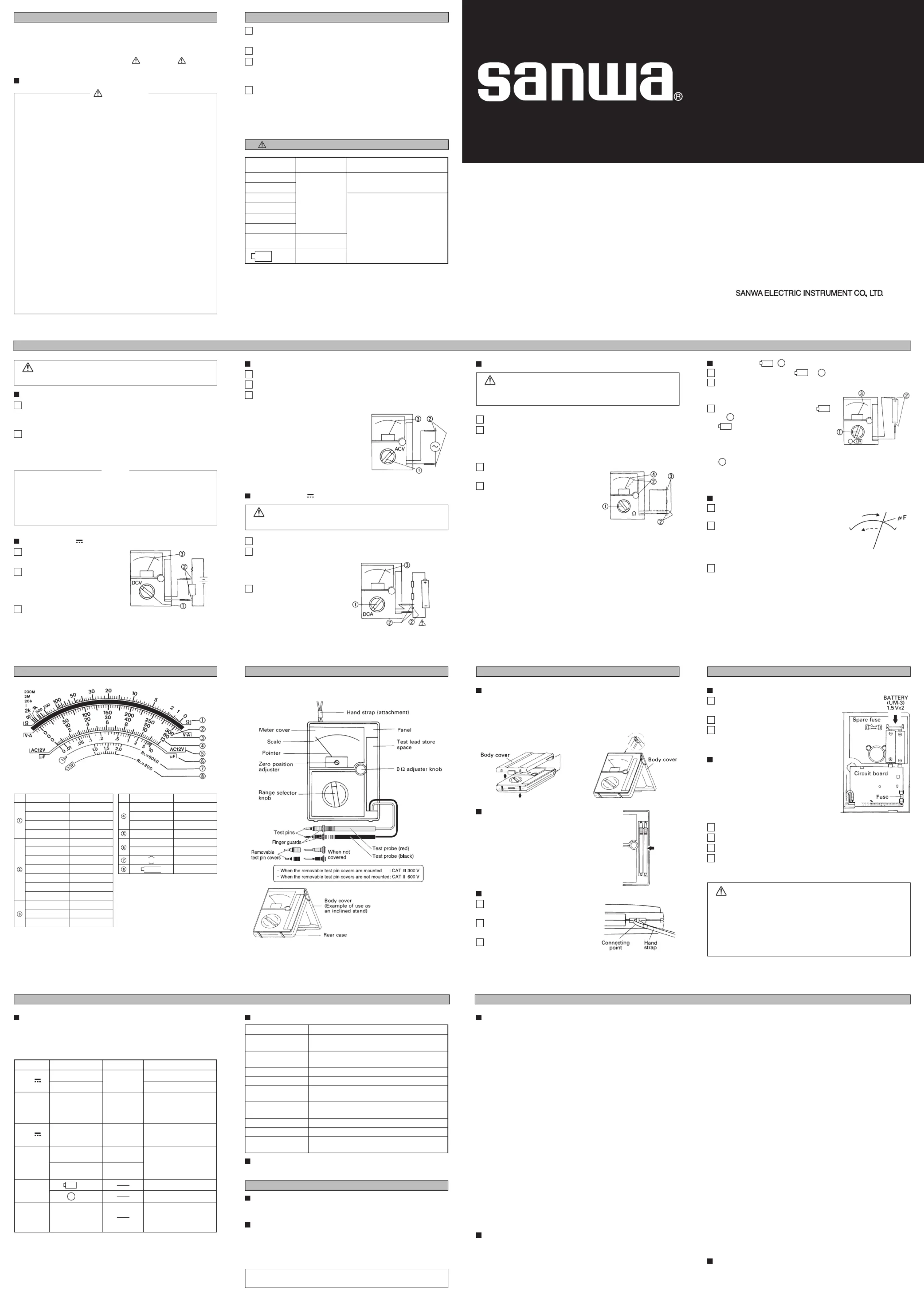
SCALE READING
ΩX100 kX100 k
ΩX1 kX1 k
ΩX10X10
ΩX1X1
DCV 30X0.1
DCV 3X0.01
DCV 0.3X0.001
ACV 300X1
ACV 30X0.1
DCA 0.3X0.001
DCA 30 mX0.1
DCV 600X10
ACV 600X10
DCA 60 µX1
DCV 120X10
DCV 12X1
ACV 120X10
ACV 12X1
µF X100X100
µF X1X1
X1
X1
1.5V
1.5V
NAMES OF COMPONENTSBODY COVER, TEST LEADS, HAND STRAP
Use of Cover (example for the body cover)
When this tester is out of use:
Attach the cover to the panel face for safekeeping.
When measuring:
Attachiteithertotherearcasesid e
or use it as a stand as illustrated.
Store of Test Leads
Whenplacingthetestleadsinth e
storingspace,rollittimes,thenpu 3 t
inthetestpinsidefirstforstore in
theplace(testleadstorespace) as
illustrated.
Attachment of Hand Strap
1Loosen the screw fixing the rear
case and remove it.
2 -Handstrapisattachedtocon
necting point.
3 dPutbacktherearcasewasan
fix it with the screw.
MAINTENANCE
How to Replace Battery
1 rLoosenthescrewfixingtherea
case and remove it.
2Replace R6 (UM-3) dry battery.
3 itPutbacktherearcasewhere
was and fix it with the screw.
How to Replace Fuse
Ifanoverloadabovelightingvoltag e
(about100V)isappliedtoDC A
and n t f is wn toΩrages,heuseblo
prottthe circuit.ec
1.Loosen the screws fixing the rear case and remove it
2.Pull out the fuse out of holder on the circuit board and replace it
3.Put back the rear case where it was and tighten the screws
4 eCheckandseewhetherornotindicationsofrespectiv
ranges are normal (check other parts for any failures).
WARNING
•Be sure to use the fuse in same rating (0.5 A/250 V)
so as to ensure safety and performance of tester.
•Do not absolutely use the fuse in different rating or
short-circuit fuse holder terminals with copper wire.
•When operator removes the rear case, do not touch
the internal parts or wire with hand.
Measurement Range and Accuracy
Accuracy assurance range:23±2 75 %RH max.℃
No condensation
Attitude:Horizontal (±5°)
ACV accuracy in the case of sine wave AC.
FunctionFull scale valueAccuracyRemarks
DCVCV
0.3
3-12-30-120-600
±3 %
against
full scale
Input impedance 5 kΩ
Input impedance 20 k/VΩ
ACV ~
12-30-120-300-600
±3 %
against
full scale
Input impedance 9 k/VΩ
Freq. (within ±3 % f.s.)
30 Hz-70 kHz (12 V range)
30 Hz-20 kHz (30 V range)
60 µ-30 m-0.3
±3 %
against
full scale
DCACV
Voltage drop 0.3 V
Not including the resist-
ance of the fuse
Ω
2 k-20 k-2 M
(X1) (X10) (X1 k)
200 M
(X100 k)
±3 % of arc
±5 % of arc
Center value 20 Ω
Max. value 2 kΩ
Release voltage 3 V
Battery
load
voltage
2.0 V
2.0 V
Load resistance 20 Ω
Load resistance 60 kΩ
Capacity
(µF)
10-1000
Pointer indication of the
maximum move by
charged current in the
capacitor.
Factory-preinstalled built-in battery
A battery for monitoring is preinstalled before shipping, therefore
itmayrundownsoonerthanthebatterylifespecifiedinth e
instruction manual.
The ”battery for monitoring” is a battery to inspect the functions
and specifications of the product.
Accessories
Instruction manual 1, Hand strap 1,
Spare fuse 1 (contained in the rear case)
General Specification
noitacificepSsmetI
Drop shock proof
Taut-band structure is adopted in the meter section.
The meter section is designed to withstand shock.
Cricuit protection
The circuit is proected by fuse even when voltage of up
to AC 250 V is impressed on each range for 5 seconds.
Internal battery
Internal fuse
R6 (IEC) or UM-3 1.5 V X 2
0.5 A/250 V Ø5 X 20 mm Fast acting fuse
Accuracy assurance
Temperature/Humidity range
23±2 , 75 %RH max. no condensation℃
Operating temperature
and humidity range
0 ~ 43 , 80 %RH max. no condensation℃
Withstand voltage
Dimensions and Mass
3 kV AC (1 min.) between input test pin and case
159.5 X 129 X 41.5 mm/ approx. 320 g
Optional Accessories
Alligator clip CL-14 IC test clip TL-9IC
APPLICATION AND FEATURE
Application
This instrument is portable multitester designated for meas-
urement of weak current circuits.
Feature
•Our htechnologyhasmadeitpossibletomeasurehig
resistance (up to maximum 200 M) with low voltage.Ω
•Band smeterofdropshocktypewithhighsensitivityha
been employed.
The specifications described in this manual are subject to
chage without notice.
Warranty and Provision
Sanwaoffers comprehensivewarrantyservices toitsend-user s
andtoitsproductresellers.UnderSanwa'sgeneralwarrant y
policy,eachinstrumentiswarrantedtobefreefromdefects in
workmanshipormaterialundernormalusefortheperiod of
one (1) year from the date of purchase.
Thiswarrantypolicy isvalidwithinthe countryofpurchaseonly ,
andappliedonlytotheproductpurchasedfromSanwaauthor -
ized agent or distributor.
Sanwareservesthe righttoinspect allwarrantyclaimsto deter-
minetheextenttowhichthewarrantypolicyshallapply.Thi s
warrantyshallnotapplytofuses,testleads,disposablesbatter -
ies,oranyproductorparts,whichhavebeensubjecttoone of
the following causes:
1.A sfailureduetoimproperhandlingorusethatdeviate
from the instruction manual.
2.A failure due to inadequate repair or modification by peo-
ple other than Sanwa service personnel.
3.A tfailureduetocausesnotattributabletothisproduc
such as fire, flood and other natural disaster.
4.Non-operation due to a discharged battery.
5.A failure or damage due to transportation, relocation or
dropping after the purchase.
Repair
Cumersaskedtoprovidethefollowiinrmiosto are ng foatn
when requesting services:
1.Customer name, address, and contact information
2.Description of problem
3.Description of product configuration
4.Model Number
5.Product Serial Number
6.Proof of Date-of-Purchase
7.Where you purchased the product
1)Prior to requesting repair,please check the following:
Capacity of the built-in battery, polarity of installation and
discontinuity of the test leads.
2)Repair during the warranty period:
The failed meter will be repaired in accordance with the
conditions stipulated in Warranty and Provision.
3)Repair after the warranty period has expired:
Insomecases,repairandtransportationcostmaybecom e
higherthanthepriceoftheproduct.PleasecontactSanw a
authorized agent / service provider in advance.
The minimum retention period of service functional parts
is 6 years after the discontinuation of manufacture. This
retentionperiodistherepairwarrantyperiod.Pleas e
note, however, if such functionalparts become unavail-
able for reasons of discontinuation of manufacture, etc.,
the retention period may become shorter accordingly.
4)Precautions when sending the product to be repaired
Toensurethesafetyoftheproductduringtransporta -
tion,placetheproductinboxthatislargerthanth a e
product 5 times or more in volume and fill cushion mate-
rialsfullyandthenclearlymark”RepairProduc t
Enclosed” on the box surface. The cost of sending and
returning the product shall be borne by the customer.
SANWA web site
http://www.sanwa-meter.co.jp
E-mail: [email protected]
MEASURING PROCEDURE
SPECIFICATIONS
AFTER-SALE SERVICE
Product specificaties
| Merk: | Sanwa |
| Categorie: | Multimeter |
| Model: | SP-18D |
Heb je hulp nodig?
Als je hulp nodig hebt met Sanwa SP-18D stel dan hieronder een vraag en andere gebruikers zullen je antwoorden
Handleiding Multimeter Sanwa

22 Juni 2025
22 Juni 2025
7 December 2024
24 Januari 2024
6 Januari 2024
6 Januari 2024
6 Januari 2024
6 Januari 2024
5 Januari 2024
5 Januari 2024
Handleiding Multimeter
Nieuwste handleidingen voor Multimeter
2 Juni 2026
18 Mei 2026
6 Mei 2026
6 Mei 2026
21 April 2026
21 April 2026
21 April 2026
20 April 2026
20 April 2026
20 April 2026