Samsung UA65AU8000S Handleiding
Bekijk gratis de handleiding van Samsung UA65AU8000S (3 pagina’s), behorend tot de categorie Televisie. Deze gids werd als nuttig beoordeeld door 147 mensen en kreeg gemiddeld 4.8 sterren uit 74 reviews. Heb je een vraag over Samsung UA65AU8000S of wil je andere gebruikers van dit product iets vragen? Stel een vraag
Pagina 1/3

Multimedia Steckdosen
Multimedia sockets
Best.-Nr. 33 15 xx
Order no. 33 15 xx
Bedienungs- und
Montageanleitung
Operation and
installation instructions
3 x Cinch/S-Video Steckdose
Best.-Nr. 33 1532 xx
USB/3,5 mm Audio Steckdose
Best.-Nr. 33 1539 xx
VGA Steckdose
Best.-Nr. 33 1540 xx
VGA Steckdose mit Schraub-
Liftklemmen
Best.-Nr. 33 1541 xx
High Denition Steckdose
Best.-Nr. 33 1542 xx
High Denition Steckdose mit
90°-Steckanschluss
Best.-Nr. 33 1543 xx
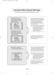
Sicherheitshinweise
Einbau und Montage elektrischer Geräte
dürfen nur durch Elektrofachkräfte erfolgen.
Dabei sind die geltenden Unfallverhütungs-
vorschriften zu beachten.
Bei Nichtbeachtung der Anleitung können
Schäden am Gerät, Brand oder andere
Gefahren entstehen.
Eine einwandfreie Signalübertragung ist nur
bei Verwendung von passendem Zubehör
sowie der Einhaltung der spezizierten maxi-
malen Leitungslängen und des minimal zuläs-
sigen Abstands von 0,3 m zu stromführenden
Leitungen und Störquellen (EVGs, Dimmer,
ESL, ..) gewährleistet.
Diese Bedienungsanleitung ist Bestandteil
des Produkts und muss beim Endanwender
verbleiben.
Geräteaufbau
Frontansicht ( ), Rückansicht ( )a b
3 x Cinch/S-Video Steckdose (Bild 1)
(1) S-Video-Buchsen
(2) Cinch-Buchsen Video (gelb)
(3) Cinch-Buchsen Audio (rot, weiß)
USB/3,5 mm Audio Steckdose (Bild 2)
(4) 3,5 mm Klinken-Buchsen
(5) USB-Buchsen
VGA Steckdose (Bild 3)
(6) VGA-Buchsen
VGA Steckdose mit Schraub-Liftklemmen
(Bild 4)
(7) VGA-Buchsen
(8) Anschlussklemmen
High Denition Steckdose (Bild 5)
(9) HDMI™- Buchsen
High Denition Steckdose mit 90°-Steck-
anschluss (Bild 6)
(10) HDMI™-Buchsen
Funktion
Die Multimedia Steckdosen dienen der Verbin-
dung von Ein- und Ausgabegeräten zur Über-
tragung von Audio-/Videosignalen und Daten.
Die verfügbaren Funktionen sind abhängig
von den angeschlossenen Geräten. Zur Aus-
wahl der passenden Steckdose die Hersteller-
angaben der Anschlussgeräte beachten.
Bestimmungsgemäßer Gebrauch
- Ausschließlich zum Gebrauch in Innenberei-
chen geeignet
- In Mehrfachkombinationen einsetzbar
- Unterputz-Montage in Einbaudose nach
DIN VDE 0606
- Anschluss der Audio-/Videogeräte per
„Plug & Play“
Bedienung
VORSICHT!
Fehlfunktion der Geräte durch Ver wen-
dung nicht genormter Anschlussleitun gen
und Stecker.
Die Geräte können zer stört werden.
Nur zugelassene Anschlussleitungen
und Stecker verwenden.
Multimediageräte anschließen
<Stecker der Verbindungsleitung von der Sig nal-
quelle, wie z. B. DVD- oder MP3-Player, in die
Buchse der Multimedia Steckdose stecken.
<Stecker der Verbindungsleitung vom Wieder-
gabegerät, wie z. B. LCD-/Plasma-Fernseher
oder Musikanlage, in die Buchse einer zwei-
ten Multimedia Steckdose stecken.
Stecker gerade und mit geringem Kraftauf-
wand in die Buchsen stecken. Durch Ver-
drehen oder Verkanten der Stecker können
sich die Kontakte verbiegen.
Anwendungsbeispiele
Anschluss Geräte
Cinch Audioanlagen, AV-Receiver,
Aktiv-Lautsprecher ..
S-Video SAT-Receiver, Fernseher, Pro-
jektoren, iPod-Dockingstationen,
Videokameras ..
USB iPods, Drucker, Speichermedien,
Digitalkameras ..
3,5 mm
Audio
MP3-Player, CD/DVD-Player,
Soundkarten, Audioanlagen ..
VGA PC/Laptops, Projektoren,
Monitore ..
High
Denition
Hochauösende Plasma/
LCD-Fernseher, SAT-Receiver,
Pro jektoren, Spielekonsolen,
DVD-/Blu-ray Player, DVD-/
HDD-Recorder, Videokameras ..
Informationen für Elektrofachkräfte
Montage
Multimedia Steckdose anschließen/montieren
Das Verbindungskabel ist verlegt, die Einbau-
dose ist in der Wand montiert.
Empfehlung: Kaiser „Electronic-Dose“ (Art.
Nr. 1068-02 oder 9062-74) zur Einhaltung der
zulässigen Biegeradien verwenden.
<Stecker des Verbindungskabels hinten in die
dafür vorgesehene Buchse der Multimedia
Steckdose stecken (Bild 7, 11) oder
<Bei Verwendung der VGA Steckdose mit
Schraub-Liftklemmen die Aderenden vorberei-
ten und entsprechend der Anschlussbelegung
(Bild 8, Tab. 1) an den Klemmen anschließen.
PIN/
Klemme
Übertragungs-
signal
Ader
1 Rot Koaxial-Ader
2 Grün Koaxial-Ader
3 Blau Koaxial-Ader
4* Monitor ID Bit 2 Twisted Pair-
Ader (optionaler
Anschluss)
5 Masse Twisted Pair-
Ader
6 Rot Masse Koaxial-Schirm
7 Grün Masse Koaxial-Schirm
8 Blau Masse Koaxial-Schirm
9 – –
10* Synchron
Masse
Twisted Pair-
Ader
PIN/
Klemme
Übertragungs-
signal
Ader
11* Monitor ID Bit 0
oder digitale
Masse
Twisted Pair-
Ader (optionaler
Anschluss)
12 Monitor ID Bit 1 Twisted Pair-
Ader (optionaler
Anschluss)
13 Horizontale
Synchronisation
Ader 1
14 Vertikale
Synchronisation
Ader 2
15 Monitor ID Bit 3 –
SHL Gehäuse
Schirmung
Äußere
Schirmung
* werden zusammen an 1 Klemme angeschlossen
Tabelle 1: Kontaktbelegung der VGA Steck-
dose mit Schraub-Liftklemmen
<Einsatz (Bild 7, 12) lagerichtig über den
Tragring mit der Einbaudose verschrauben.
<Zentralstück (Bild 7, 13) in den Rahmen legen.
<Zentralstück zusammen mit dem Rahmen
mittels Klemmfedern (Bild 7, 14) auf den
Einsatz stecken.
Die Multimedia Steckdose kann in Betrieb
genommen werden.
Inbetriebnahme
VORSICHT!
Kurzschluss beim Anschluss einge-
schalteter Geräte.
Geräte können zerstört werden.
Vor dem Anschließen alle Geräte
ausschalten.
Funktionsprüfung durchführen
Multimediageräte sind angeschlossen.
<Gewünschte Funktionalität aktivieren und
Sig nalübertragungen an der Signalquelle und
dem Wiedergabegerät prüfen, z. B. Abspielen
einer DVD und Bild-/Tonwiedergabe am
Fernsehgerät.
Die Multimedia Steckdose ist betriebsbereit.
Anhang
Technische Daten
Umgebungstemperatur: -5 bis +45 °C
Cinch-Buchsen
Nennspannung DC 50 V=
Frequenzbereiche
- Audio 20 Hz bis 20 KHz
- Video ≤ 160 MHz
Kontaktwiderstand ≤ 20 mΩ
Isolationswiderstand ≥ 100 mΩ
Spannungsfestigkeit AC 500 V~ (50/60 Hz)
bei 1 min 2 mA
Steck- und Abziehkräfte 3 N bis 25 N
- Zyklus 1000 Steck-/Abziehvorgänge
Anschluss
- Doppelbuchsen gelb (Video)
weiß (Audio, links)
rot (Audio, rechts)
- Kontaktmaterial vergoldet
S-Video-Buchsen
Nennspannung DC 50 V=
Frequenzbereich
- Video ≤ 160 MHz
Kontaktwiderstand ≤ 80 mΩ
Isolationswiderstand ≥ 50 mΩ
Spannungsfestigkeit AC 500 V~ (50/60 Hz)
bei 1 min 2 mA
Steckkräfte ≤ 44,1 N
Abziehkräfte 5,88 N bis 29,4 N
1a 1b
(1)
(2)
(3)
7(12) (13)
(14)(11)
- Zyklus 1000 Steck-/Abziehvorgänge
Anschluss
- Doppelbuchse S-Video
- Kontaktmaterial vergoldet
USB-Buchsen
Standard USB 3.0
Datenrate max. 5 Gbit/s
Anschluss
- Doppelbuchse Type A, 180°
3,5 mm Audio-Buchsen
Nennspannung DC 50 V=
Frequenzbereich
- Audio 20 Hz bis 20 KHz
Kontaktwiderstand ≤ 20 mΩ
Isolationswiderstand ≥ 100 mΩ
Spannungsfestigkeit AC 500 V~ bis 2000 V~
DC 800 V=
Steck- und Abziehkräfte 4,9 N bis 14,7 N
- Zyklus 2000 Steck-/Abziehvorgänge
Anschluss
- Doppelbuchse 3,5 mm Audio „Stereo“, 180°
- Kontaktmaterial vergoldet
HDMI™-Buchsen
Standard 1.3/Category 2
Unterstützung der HDMI™
Technologie (V 1.3 mit Deep Color)
Auösung ≤ 1080p
(1920 x 1080 Pixel)
Frequenzbereich vertikal 50 bis 85 Hz
Datenrate max.8,16 Gbit/s
Anschluss
- Doppelbuchse HDMI™ Typ A, 180°/90°
- Kontaktmaterial vergoldet
VGA-Buchsen
Auösung ≥ 800 x 600 Pixel
≤ 1280 x 1024 Pixel
S-VGA kompatibel
Frequenzbereich
- Video ≤ 160 MHz
Kontaktwiderstand ≤ 30 mΩ
Isolationswiderstand ≥ 1000 mΩ
Spannungsfestigkeit AC 1000 V~ (50/60 Hz)
bei 1 min 2 mA
Steckkräfte 43,9 N
Abziehkräfte 3,92 N
- Zyklus 500 Steck-/Abziehvorgänge
Anschluss
- Buchse 15-polig D-Subminiatur, 180°
- Leiterquerschnitt Schraub-Liftklemme
≤ 1,5 mm2
Hilfe im Problemfall
Kein Signal am Wiedergabegerät nach
Einschalten der Signalquelle.
Ursache 1: Wiedergabegerät ist nicht
ein geschaltet.
<Wiedergabegerät einschalten.
Ursache 2: Stecker hat sich gelöst.
<Alle Steckverbindungen auf korrekten Sitz
überprüfen.
Kein Videosignal am Wiedergabegerät nach
Einschalten der Signalquelle.
Ursache 1: Signalquelle wird vom Wiedergabege-
rät nicht erkannt.
<Manuelle Wahl der Signalquelle über Fernbe-
dienung oder Kanal-Wahltasten des Wieder-
gabegerätes.
Ursache 2: VGA-Ausgang der Signalquelle ist
nicht aktiviert.
<VGA-Ausgang aktivieren. Angaben des Ge-
räteherstellers beachten.
8
Kein Audiosignal am Wiedergabegerät nach
Einschalten der Signalquelle.
Ursache 1: Lautstärkeregelung an der Signal-
quelle oder am Wiedergabegerät zu niedrig ein-
gestellt.
<Lautstärke erhöhen.
Ursache 2: Der Ton am Wiedergabegerät ist
stumm geschaltet.
<Stummschaltung deaktivieren.
Angaben des Geräteherstellers beachten.
Gewährleistung
Technische und formale Änderungen am Produkt,
soweit sie dem technischen Fortschritt dienen,
behalten wir uns vor.
Wir leisten Gewähr im Rahmen der gesetzlichen
Bestimmungen.
Im Gewährleistungsfall bitte an die Verkaufsstelle
wenden.
Berker GmbH & Co. KG
Zum Gunterstal
66440 Blieskastel/Germany
Tel.: + 49 6842 945 0
Fax: + 49 6842 945 4625
E-Mail: info@berker.de
www.berker.com
12/2020
6LE007634A
(1)
(6)
(2)
(7)
(3)
(8)
(12)
(13)
(14)
(SHL) (4, 10, 11 )
(5)
2a
(4)
(5)
(7)
(8)
4a 4b
3a 3b
(6)
5a 5b
(9)
6a 6b
(10)
2b
(5)
(10) (6)
(15)
(1)
(11)
(SHL)

3 x cinch/S-Video socket
Order no. 33 1532 xx
USB/3.5 mm audio socket
Order no. 33 1539 xx
VGA socket
Order no. 33 1540 xx
VGA socket with screw-in lift
terminals
Order no. 33 1541 xx
High denition socket
Order no. 33 1542 xx
High denition socket with 90° plug
connection
Order no. 33 1543 xx
Safety instructions
Electrical equipment must only be installed
and assembled by qualied electricians.
Always follow the relevant accident preven-
tion regulations.
Failure to comply with these instructions may
result in damage to the device, re or other
hazards.
Proper signal transmission is only ensured
when the appropriate accessories are used
and the specied maximum cable lengths are
observed, as well as the minimum permissible
distance of 0.3 m from current-carrying cables
and sources of interference (electronic bal-
lasts, dimmers, ESLs, etc.) are observed.
These operating instructions are an integral
component of the product, and must be
retained by the end user.
Structure of the device
Front view ( ), rear view ( )a b
3 x cinch/S-Video socket (Figure 1)
(1) S-Video jacks
(2) Cinch video jacks (yellow)
(3) Cinch audio jacks (red, white)
USB/3.5 mm audio socket (Figure 2)
(4) 3.5 mm jack sockets
(5) USB jacks
VGA socket (Figure 3)
(6) VGA jacks
VGA socket with screw-in lift terminals
(Figure 4)
(7) VGA jacks
(8) Connection terminals
High denition socket (Figure 5)
(9) HDMI™ jacks
High denition socket with 90° plug
connection (Figure 6)
(10) HDMI™ jacks
Function
The multimedia sockets serve to connect input
and output devices for transmission of audio/
video signals and data.
The available functions depend on the devices
that are connected. To select the suitable
socket, note the information from the manu-
facturer of the connected devices.
Intended use
- Only suitable for use in indoor areas
- Can be used in multiple combinations
- Flush-mounting in wall box according to
DIN VDE 0606
- Connection of audio/video devices via
„Plug&Play“
Operation
CAUTION!
The use of non-standardised connecting
cables and connectors can cause device
malfunctions.
The devices may be destroyed.
Use only approved connecting cables
and connectors.
Connecting multimedia devices
<Insert connector of the connecting cable from
the signal source, e.g. from a DVD or MP3
player, into the jack of the multimedia socket.
<Insert connector of the connecting cable from
a playback device, e.g. from an LCD/plasma
tele vision or stereo system, into the jack of a
second multimedia socket.
Insert connectors into the jacks straight and
without using force. Twisting or tilting the con-
nector may deform the contacts.
Application examples
Connection Devices
Cinch Audio systems, AV receivers,
active loudspeakers ..
S-Video SAT receivers, televisions, pro-
jectors, iPod docking stations,
video cameras ..
USB iPods, printers, storage media,
digital cameras ..
3,5 mm au-
dio
MP3 players, CD/DVD players,
sound cards, audio systems ..
VGA PCs/laptops, projectors,
monitors ..
High
denition
High denition plasma/LCD
tele visions, SAT receivers,
projectors, game consoles,
DVD/Blu-ray players, DVD/HDD
recorders, video cameras ..
Information for electricians
Assembly
Connecting and installing the multimedia socket
The connecting cable has been laid, the wall box
is installed in the wall.
Recommendation: use Kaiser “Electronics
Box” (Art. no. 1068-02 or 9062-74) in order to
maintain the permissible bending radii.
<Insert connector of the connecting cable into
the corresponding jack on the rear of the mul-
timedia socket (Figure 7, 11) or
<When using the VGA socket with screw-in lift
terminals, prepare the wire ends and connect
to the terminals according to the terminal
assignment (Figure 8, Table 1).
PIN/
Terminal
Transmission
signal
Wire
1 red Coaxial wire
2 green Coaxial wire
3 blue Coaxial wire
4* Monitor ID bit 2 Twisted pair
wire (optional
connection)
5 Ground Twisted pair
wire
6 red ground Coaxial
shielding
7 green ground Coaxial
shielding
8 blue ground Coaxial
shielding
9 – –
PIN/
Terminal
Transmission
signal
Wire
10* Synchronous
ground
Twisted pair
wire
11* Monitor ID bit 0
or digital ground
Twisted pair
wire (optional
connection)
12 Monitor ID bit 1 Twisted pair
wire (optional
connection)
13 Horizontal
synchronisation
wire 1
14 Vertical
synchronisation
wire 2
15 Monitor ID bit 3 -
SHL Housing shielding External
shielding
* Are connected together at one terminal
Table 1: Contact pinouts of the VGA socket
with screw-in lift terminals
<Screw insert (Figure 7, 12) to the wall box in
the right orientation via the supporting ring.
<Place centre plate (Figure 7, 13) into the
frame.
<Mount centre plate together with the frame on
the insert using clamp springs (Figure 7, 14).
The multimedia wall box can be commissioned.
Commissioning
CAUTION!
Short-circuit if devices that are switched
on are connected.
Devices may be destroyed.
Switch all devices o before connecting
them.
Carrying out a functional test
Multimedia devices are connected.
<Activate the desired functions and check the
signal transmission at the signal sources and
the playback device, e.g. play a DVD and
check picture/sound reproduction on a tele-
vision set.
The multimedia socket is ready for operation.
Appendix
Technical data
Ambient temperature: -5 to +45 °C
Cinch jacks
Rated voltage DC 50 V=
Frequency ranges
- Audio 20 Hz to 20 KHz
- Video ≤ 160 MHz
Contact resistance ≤ 20 mΩ
Insulation resistance ≥ 100 mΩ
Electric strength AC 500 V~ (50/60 Hz)
for 1 min 2 mA
Insertion and removal forces 3 N to 25 N
- Cycles 1000 insertion/removal operations
Connection
- Double jacks yellow (video)
white (audio, left)
red (audio, right)
- Contact material gold-plated
S-Video jacks
Rated voltage DC 50 V=
Frequency range
- Video ≤ 160 MHz
Contact resistance ≤ 80 mΩ
Insulation resistance ≥ 50 mΩ
Electric strength AC 500 V~ (50/60 Hz)
for 1 min 2 mA
Insertion forces ≤ 44.1 N
1a 1b
(1)
(2)
(3)
7(12) (13)
(11)
Removal forces 5.88 N to 29.4 N
- Cycles 1000 insertion/removal operations
Connection
- Double jack S-Video
- Contact material gold-plated
USB jacks
Standard USB 3.0
Date rate max. 5 Gbit/s
Connection
- Double jack Type A, 180°
3.5 mm audio jacks
Rated voltage DC 50 V=
Frequency range
- Audio 20 Hz to 20 KHz
Contact resistance ≤ 20 mΩ
Insulation resistance ≥ 100 mΩ
Electric strength AC 500 V~ to 2000 V~
DC 800 V=
Insertion and removal forces 4.9 N to 14.7 N
- Cycles 2000 insertion/removal operations
Connection
- Double jack 3.5 mm Audio “Stereo”, 180°
- Contact material gold-plated
HDMI™ jacks
Standard 1.3/Category 2
Support for HDMI™ technology
(V 1.3 with Deep Color)
Resolution ≤ 1080p
(1920 x 1080 pixels)
Vertical frequency range 50 to 85 Hz
Date rate max. 8.16 Gbit/s
Connection
- Double jack HDMI™ type A, 180°/90°
- Contact material gold-plated
VGA jacks
Resolution ≥ 800 x 600 pixels
≤ 1280 x 1024 pixels
S-VGA compatible
Frequency range
- Video ≤ 160 MHz
Contact resistance ≤ 30 mΩ
Insulation resistance ≥ 1000 mΩ
Electric strength AC 1000 V~ (50 / 60 Hz)
for 1 min 2 mA
Insertion forces 43.9 N
Removal forces 3.92 N
- Cycles 500 insertion/removal operations
Connection
- Jack 15pole D-subminiature, 180°
- Conductor Screw-in lift terminal
cross-section ≤ 1.5 mm2
Troubleshooting
No signal at the playback device after the
signal sources is switched on.
Cause 1: Playback device is not switched on.
<Switch on playback device.
Cause 2: Loose connector.
<Check that all connections are properly
seated.
No video signal at the playback device after
the signal sources is switched on.
Cause 1: Signal source is not recognised by the
playback device.
<Manual selection of the signal source using
remote control or channel selection buttons of
the player.
Cause 2: VGA output of the signal source is not
activated.
<Activate VGA output. Note information of the
device manufacturer.
8
No audio signal at the playback device after
the signal sources is switched on.
Cause 1: Volume control on the signal source or
on the playback device is set too low.
<Increase volume.
Cause 2: The audio on the playback device is set
to mute.
<Deactivate the mute function. Note information
of the device manufacturer.
Warranty
We reserve the right to make technical and for-
mal changes to the product in the interest of tech-
nical progress.
Our products are under guarantee within the
scope of the statutory provisions.
If you have a warranty claim, please contact the
point of sale or ship the device postage free with
a description of the fault to the appropriate re-
gional representative.
(1)
(6)
(2)
(7)
(3)
(8)
(12)
(13)
(14)
(SHL)
(4, 10, 11)
(5)
2a
(4)
(5)
(7)
(8)
4a 4b
3a 3b
(6)
5a 5b
(9)
6a 6b
(10)
2b
(5)
(10) (6)
(15)
(1)
(11)
(SHL)
Product specificaties
| Merk: | Samsung |
| Categorie: | Televisie |
| Model: | UA65AU8000S |
Heb je hulp nodig?
Als je hulp nodig hebt met Samsung UA65AU8000S stel dan hieronder een vraag en andere gebruikers zullen je antwoorden
Handleiding Televisie Samsung

5 Augustus 2025

4 Augustus 2025

4 Augustus 2025
4 Augustus 2025
4 Augustus 2025
4 Augustus 2025

3 Augustus 2025

3 Augustus 2025

3 Augustus 2025

3 Augustus 2025
Handleiding Televisie
- AudioAffairs
- Sencor
- Mystery
- Blaupunkt
- Vizio
- Yamazen
- Acer
- Marantz
- Zephir
- Silvercrest
- Schaub Lorenz
- Telefunken
- Icy Box
- Norcent
- Sanyo
Nieuwste handleidingen voor Televisie
6 Augustus 2025
6 Augustus 2025
6 Augustus 2025
6 Augustus 2025

6 Augustus 2025

6 Augustus 2025

6 Augustus 2025
6 Augustus 2025
5 Augustus 2025
5 Augustus 2025