Salus RX10RF Handleiding
Salus
Smarth home
RX10RF
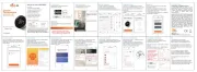
Bekijk gratis de handleiding van Salus RX10RF (2 pagina’s), behorend tot de categorie Smarth home. Deze gids werd als nuttig beoordeeld door 67 mensen en kreeg gemiddeld 4.7 sterren uit 34 reviews. Heb je een vraag over Salus RX10RF of wil je andere gebruikers van dit product iets vragen? Stel een vraag
Pagina 1/2

I N S T AL L E R / U S E R M A N U A L
Wireless Receiver Unit
Models: RX10RF
www.salus-controls.com
SALUS Controls plc
SALUS House
Dodworth Business Park South,
Whinby Road,
Dodworth, Barnsley S75 3SP, UK.
SALES: T: +44 (0) 1226 323961
E: sales@salus-tech.com
TECHNICAL: T: +44 (0) 1226 323961
E: tech@salus-tech.com
For PDF Installation guide please go to
www.salus-controls.com
Maintaining a policy of continuous product development SALUS
Controls plc reserve the right to change specication, design and
materials of products listed in this brochure without prior notice.
SALUS Controls is a member of the Computime Group
00086/2 Issue Date: Dec 2016
SALUS Controls warrants that this product will be free from any defect in materials or
workmanship, and shall perform in accordance with its specication, for a period of ve
years from the date of installation. SALUS Controls sole liability for breach of this warranty
will be (at its option) to repair or replace the defective product.
Customer Name: ..........................................................................................................
Customer Address: .......................................................................................................
................................................................ Post Code: ...................................................
Tel No: .................................................... Email: ..........................................................
Engineers Company: ....................................................................................................
Tel No: .................................................... Email: ..........................................................
Instalation Date: ..........................................................................................................
Engineers Name: .........................................................................................................
Engineers Signature: ...................................................................................................
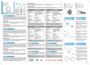
WARRANTYTECHNICAL DETAIL
INSTALLATION
Model RX10RF
Type Wired system receiver designed for 230VAC
heating applications
Control ON-OFF control
Environment Ratings
Operating Temperature 0 ºC to +50 ºC
Storage Temperature -20 ºC to +60 ºC
Operating Humidity 5-95 %RH
Switch Voltage 0-230VAC 16AMP
Power Source 230Vac 50Hz
User Interface Slide switch, Bi Colour LED, RED/GREEN
Operating Temperature 0 to 50 ºC
Storage Temperature -20ºC to 60ºC
Frequency 2.4 GHz
Approval CE
Terminal Function
COM Common Contact (volt free input)
NO Normally Open Contact (volt free output)
Earth Parking
L Incoming Mains - Live
N Incoming Mains - Neutral
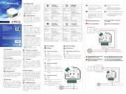
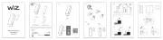
Clip the front of the unit back on
by aligning the ttings and
pushing into place.
Securely screw the front of
the receiver in place.
Wire up the receiver using
one of the schematics*.
4
5
1
2
3
4
5
6
Loosen the screws at the bottom
of the receiver unit.
Unclip the front of the unit.
Fit the back of the receiver unit to the
wall using the ttings supplied.
1 2
3
Ensure Coordinator
is powered up and
ready for pairing.
Reset Button
If for any reason the system receiver stops operating, press
reset and check system operation.
*Congured
as RX2
*Congured
as RX1
Replacing the System Receiver
If for any reason the system receiver needs to be removed/
replaced, press the delete from network.
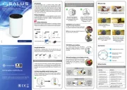
Electrical Connection Schematics Power Up
The RX10RF Receiver should be mounted in a suitable location that is both accessible
for the connection of mains and control wiring, and allows good reception of the RF
signal. The Receiver needs a 230V AC mains supply to operate, and this should be
fused appropriately (16A max.).
The Receiver should be mounted in a location where it will not come into contact
with water, moisture or condensation. There are few electrical connections required
to the RX10RF, and these connections should be made to the terminal block inside
the Receiver. No Earth connection is required for the correct and safe operation of the
RX10RF, but a parking terminal is provided to connect an Earth wire if one is present.
5sec
5sec
5sec
OR OR
*For use without internet.
Power up the receiver.
The red light will ash.
When the receiver has successfully joined the
Zigbee network, the red LED will go steady.
Please refer to VS10/VS20RF manual for system
pairing.
5sec 5sec
OR OR
Once your system
setup is complete,
remember to take
the coordinator out
of pairing mode.

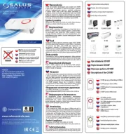
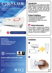
BOX CONTENTS, COMPLIANCE & SAFETY INFORMATION
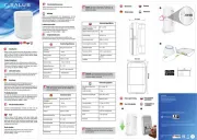
SYSTEM OVERVIEW IT600 SYSTEM CONFIGURED AS RX1 SYSTEM OVERVIEW IT600 SYSTEM CONFIGURED AS RX2
SYSTEM OVERVIEW
I NS T A L L E R A L/ U SE R MA NU
Zigbee C roordinato
Models: CO10RF
1 x Installer / User manual
Boiler Receiver x 1
2 x Screws
& 2 x Wall Plugs
For PDF Installation guide please go to www.salus-controls.com
230V AC
Sources of danger
The RX10RF must be disconnected from mains supply before removing the cover.
Emergency
Switch o the voltage to the individual thermostat wring centre or complete system.
Warning
This product must be tted by a competent person, and installation must comply
with the guidance, standards and regulations applicable to the city, country or state
where the product is installed. Failure to comply with the requirements of the relevant
guidance, standards and regulations could lead to injury, death or prosecution.
Warning
Always isolate the AC Mains supply before installing or working on any components that
require 230 VAC 50Hz supply.
INTRODUCTION
Thank you for purchasing the SALUS RX10RF system receiver. This unit is designed to
work with iT600 range of Zigbee network products.
The RX10RF can be congured as remote boiler switch or a simple single channel output
to control, a thermal actuator or zone valve. Please note the two conguratons above
can be used together in the one system.
These instructions are applicable to the SALUS model stated on the front cover of this
manual only.
Product Compliance
This product is CE compliant and meets the following EC Directives 2014/30/EU;
2014/35/EU; 2014/53/EU and 2011/65/EU.
The unit can be switched internally switched to be used on two channels, RX1 (boiler
receiver) or RX2 (single room receiver). Ensure the unit is not powered during setting
of the RX1/RX2 slide switch.
The unit is supplied with the switch in the RX1 position (Boiler
Receiver). In this mode, the unit can be wired to the boiler to
switch it on or o using the wireless signals it receives other
SALUS products on the SALUS Zigbee network
With the unit switched to RX2, the unit will act as a single room receiver. Switching
of the unit will be controlled by a paired SALUS VS10/20RF Thermostat. Depending
on its intended use, the unit can be used to switch a motorised valve, thermal
actuator or pump.
As well as being used in this way, the RX2 can be used
in conjunction with another unit set up as an RX1 (Boiler
receiver). When there is a call for heat from the thermostat
paired to the RX2 both of the wireless receivers will operate
turning on both the boiler and the motorised valve / pump.
NB: Only 1 RX1 and 1 RX2 can be used as part of a network.
*System Receiver congured
to boiler receiver. RX1
RX10RF congured
as Boiler Receiver RX1.
**System Receiver congured
to one room receiver RX2.
Max 6 TRV per the
System Receiver congured to boiler receiver RX1.
Refer to reverse side for wiring.
System receiver congured as stand alone receiver
RX2. Refer to reverse side for wiring.
RX1 & RX2 RECEIVER CONFIGURATION
The receiver can be congured as a Boiler Receiver (RX1) where
it will react to signals from a large number of components such
as SALUS wireless wiring centres, wireless thermostats used
with SALUS wireless radiator valves as well as another receiver
congured as a Stand Alone receiver (RX2).
RX10RFX Congured
as Stand Alone
receiver RX2.
1
2
3
4
User InterfaceiT600 System
AUTO – System receiver output will
switch on and o in relation to the
command from the iT600 transmitter.
The bottom slide switch in active
RED led only in AUTO means that there
is no output from the receiver.
RED and Green LED only in AUTO
means that there is an output from the
receiver. The device that the receiver is
connected to will be switched on.
Manual- system receiver output is
controlled by the bottom slide switch.
Either permenetly ON or OFF. The LED
status in manual is the same as AUTO.
VS10/20RF
RX10RF*
CO10RF
RX10RF**
VS10/20RF
UGE600
G30
UNDERFLOOR HEATING MANIFOLD
KL08RF
Product specificaties
| Merk: | Salus |
| Categorie: | Smarth home |
| Model: | RX10RF |
Heb je hulp nodig?
Als je hulp nodig hebt met Salus RX10RF stel dan hieronder een vraag en andere gebruikers zullen je antwoorden
Handleiding Smarth home Salus
28 Juli 2025
28 Juli 2025
28 Juli 2025
28 Juli 2025
28 Juli 2025
28 Juli 2025
28 Juli 2025

11 Mei 2023

26 April 2023

19 April 2023
Handleiding Smarth home
- Denver
- Asus
- Fibaro
- KanexPro
- Jung
- Renkforce
- Niceboy
- SwitchBot
- D-Link
- Strong
- Ajax
- Xiaomi
- V-Tac
- Easy Home
- Drayton
Nieuwste handleidingen voor Smarth home

8 September 2025
8 September 2025
8 September 2025
2 September 2025

2 September 2025
1 September 2025
31 Augustus 2025

14 Augustus 2025

6 Augustus 2025
4 Augustus 2025