Roland M-10MX Handleiding


Lees hieronder de đź“– handleiding in het Nederlandse voor Roland M-10MX (8 pagina's) in de categorie Mengpaneel. Deze handleiding was nuttig voor 30 personen en werd door 2 gebruikers gemiddeld met 4.5 sterren beoordeeld

Pagina 1/8
Before using this unit, carefully read the sections entitled:
“USING THE UNIT SAFELY” (p. 13–p. 14)
and
“IMPORTANT NOTES” (p. 15)
.
These sections provide important information concerning the proper operation of the unit.
Additionally, in order to feel assured that you have gained a good grasp of every feature
provided by your new unit, Owner’s manual should be read in its entirety.
The manual should be saved and kept on hand as a convenient reference.
Copyright © 2006 ROLAND CORPORATION
All rights reserved. No part of this publication may be reproduced in any form without the written
permission of ROLAND CORPORATION.
Owner’s Manual
04455178 1MP
2
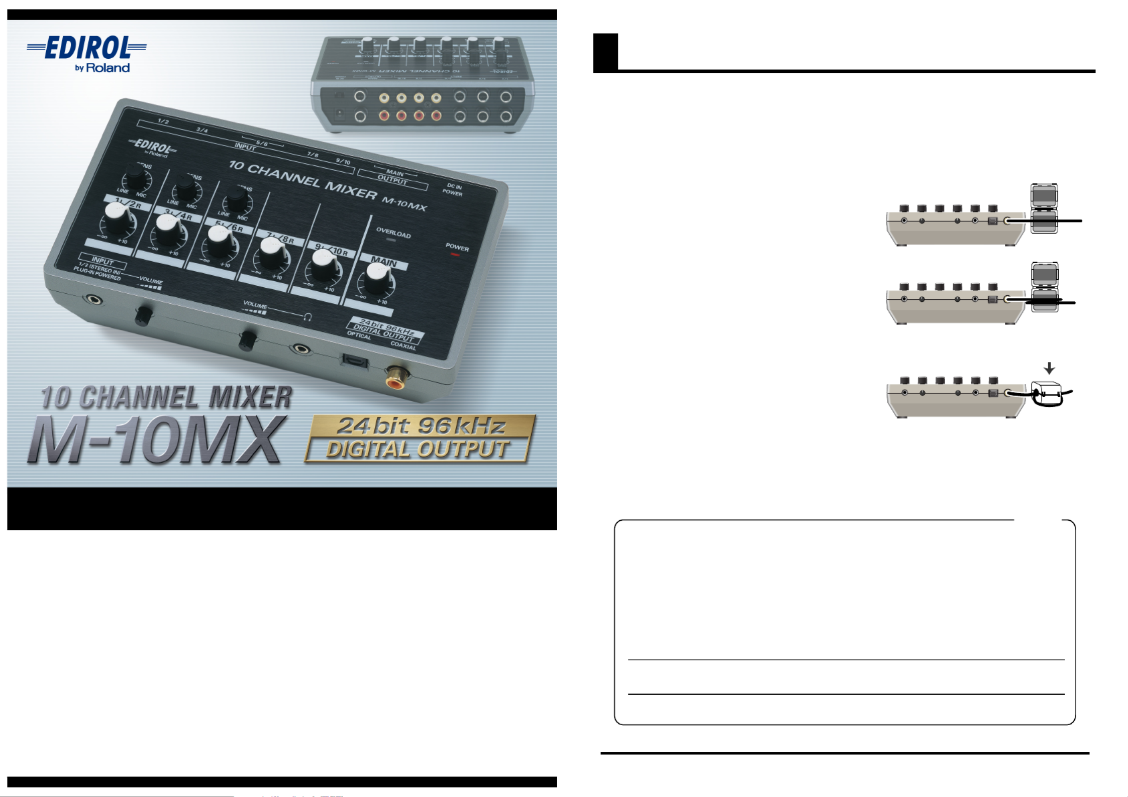
Attaching the Ferrite Core
You must attach the ferrite core before using the M-10MX.
If you connect the M-10MX’s coaxial jack to your digital device, you must attach the included ferrite
core.
This is for the purpose of preventing electromagnetic noise; do not remove it.
fig.ferraite-1
1.
Attach the ferrite core to the coaxial cable.
* You must attach it near the M-10MX.
fig.ferraite-2
2.
Wrap the coaxial cable around the ferrite
core; one turn is enough.
fig.ferraite-3
3.
Press the halves together until they click
shut.
* Be careful not to pinch your fingers when attaching the ferrite core.
* Do not damage the cable by pinching it excessively with the ferrite core.
Ferrite Core
For the USA
FEDERAL COMMUNICATIONS COMMISSION
RADIO FREQUENCY INTERFERENCE STATEMENT
This equipment has been tested and found to comply with the limits for a Class B digital device, pursuant to Part 15 of the
FCC Rules. These limits are designed to provide reasonable protection against harmful interference in a residential
installation. This equipment generates, uses, and can radiate radio frequency energy and, if not installed and used in
accordance with the instructions, may cause harmful interference to radio communications. However, there is no guarantee
that interference will not occur in a particular installation. If this equipment does cause harmful interference to radio or
television reception, which can be determined by turning the equipment off and on, the user is encouraged to try to correct the
interference by one or more of the following measures:
– Reorient or relocate the receiving antenna.
– Increase the separation between the equipment and receiver.
– Connect the equipment into an outlet on a circuit different from that to which the receiver is connected.
– Consult the dealer or an experienced radio/TV technician for help.
This device complies with Part 15 of the FCC Rules. Operation is subject to the following two conditions:
(1) This device may not cause harmful interference, and
(2) This device must accept any interference received, including interference that may cause undesired operation.
Unauthorized changes or modification to this system can void the users authority to operate this equipment.
This equipment requires shielded interface cables in order to meet FCC class B Limit.
3
Bottom
4
Panel Descriptions
SENS Knobs
These knobs adjust the input sensitivity,
allowing you to set the input level so that
the sound of each channel can be mixed
while avoiding noise or distortion.
Turning the SENS knob toward the right
will increase the sensitivity (increase the
input level), and turning it toward the
left will decrease the sensitivity (decrease
the input level).
If you’ve connected a mic to phone jacks
1–6, turn the SENS knob toward the right
near the “MIC” position.
If you’ve connected a line-level device
such as a keyboard, turn the SENS knob
toward the left near the “LINE” position.
* Each SENS knob simultaneously affects
the L/R inputs for a pair of channels.
Channel Volume Knobs
These knobs adjust the volume
of each channel. Normally, you
should use these in the marked
region.
* Each channel volume knob simultaneously
affects the L/R inputs for a pair of channels.
OVERLOAD Indicator
This indicator will light if the mixed signal is too loud.
If it lights frequently, turn the SENS knob of each
channel toward the left to reduce the input level (p. 9).
* This indicator will light 6 dB before clipping level (the level
at which clipping begins).
Plug-in Power
Compatible INPUT Jack
(stereo mini jack)
This is a input jack for connecting a
plug-in power compatible stereo mic.
The sound from the connected mic is
input to channels 1/2.
If you connect a device to the rear
panel’s INPUT 1/2 jacks, both sounds
will be mixed.
* A mono mic cannot be used.
* The SENS 1/2 knob does not affect the
input from this jack.
VOLUME Knob
This knob adjusts the volume of the
input from the connected mic.
To minimize the volume, turn this
knob all the way to the left.
Headphone Jack
(stereo mini jack)
You can connect stereo
headphones to this jack.
VOLUME Knob
This knob adjusts the
volume of the headphones.
* The volume of the
headphones is not affected
by the MAIN volume knob.
DIGITAL OUTPUT
Connector/Jack
These jacks digitally
output the same audio
signal as the OUTPUT
jacks.
Both optical and coaxial
jacks are provided, and
both can be used
simultaneously.
* No signal will be output
from these jacks if the
POWER SAVE switch is
on.
POWER Switch
This turns the power on/off.
Set this switch to “DC IN” if you’re
using the AC adaptor, or to
“BATT” if you’re using batteries;
the power will turn on, and the
POWER indicator will light.
DC IN
(AC Adaptor)
Jack
Connect the supplied AC
adaptor to this jack.
OUTPUT Jacks
(TRS phone/RCA pin jacks)
These jacks output the mixed signal.
Both phone jacks and RCA pin jacks are provided, and you
can connect to both jacks and send the output to separate
devices. These are TRS jacks, which allow you to use stereo
phone plugs for a balanced audio connection, or use mono
phone plug cables for an unbalanced connection.
* If you’re using a balanced connection, check to make sure that
the input jacks of your equipment are wired as shown below. Be
aware that on some equipment, the HOT and COLD are
reversed.
INPUT Jacks
(phone jacks, RCA pin jacks)
Channels 1–4, 5, 6 (phone jacks)
These jacks are suitable for use with electronic musical
instruments or mics. If you’re connecting a mic or other monaural
device, use the L (MONO) jack.
Channels 5, 6, 7–10 (RCA pin jacks)
These jacks are suitable for connecting desktop media production
devices or audio equipment such as CD/MD players.
Channels 5/6 provide both phone jacks and RCA pin jacks, which
can be used simultaneously.
POWER Indicator
This will light when the power is
turned on.
* If you’re operating on batteries,
the brightness of this indicator will
show the state of the batteries.
If the indicator becomes dim, you
need to replace the batteries.
MAIN Volume Knob
This knob adjusts the overall
volume for the mixed inputs of
each channel.
* The output level from the
headphone jack will not be affected
even if you use the MAIN volume
knob to lower the volume.
SAMPLE RATE Switch
Allows you to select 44.1, 48, or 96 kHz as the
sampling frequency (sample rate) of the digital
audio signal sent from DIGITAL OUTPUT.
POWER SAVE Switch
This turns the “power save” function
on/off.
If you turn this function on, the digital
output from the DIGITAL OUTPUT
connector will be turned off (no output),
reducing the power consumption.
5
Block Diagram
PHONES
VOLUME
A/D
A/D
A/D
A/DA/D
INPUT 1/2
INPUT 1/2
INPUT 1/2
INPUT 1/2INPUT 1/2
INPUT 9/10
INPUT 9/10
INPUT 9/10
INPUT 9/10INPUT 9/10
Bus R
Bus L
INPUT 1/2
INPUT 1/2
INPUT 1/2
INPUT 1/2INPUT 1/2
INPUT 3/4
INPUT 3/4
INPUT 3/4
INPUT 3/4INPUT 3/4
CHANNEL
VOLUME
CHANNEL
VOLUME
CHANNEL
VOLUME
CHANNEL
VOLUME
CHANNEL
VOLUME
INPUT 7/8
INPUT 7/8
INPUT 7/8
INPUT 7/8INPUT 7/8
INPUT 5/6
INPUT 5/6
INPUT 5/6
INPUT 5/6INPUT 5/6
INPUT 5/6
INPUT 5/6
INPUT 5/6
INPUT 5/6INPUT 5/6
SENS
SENS
SENS
SENSSENS
SENS
SENS
SENS
SENSSENS
SENS
SENS
SENS
SENSSENS
SENS
SENS
SENS
SENSSENS
SENS
SENS
SENS
SENSSENS
VOLUME
VOLUME
VOLUME
VOLUMEVOLUME
SENS
SENS
SENS
SENSSENS
MAIN
VOLUME
OVER
OVER
OVER
OVEROVER
LOAD
LOAD
LOAD
LOADLOAD
MAIN OUTPUT
PHONES
DIGITAL OUTPUT
1/4" Phone
1/4" Phone
1/4" Phone
RCA
RCA
RCA
Stereo Mini
TRS Impedance Balanced
Plug-in power
compatible Stereo Mini
COAXIAL
OPTICAL
RCA
Main Features
The M-10MX is a lightweight and compact mixer providing 10 channels of input (5 stereo channels),
and is an ideal choice for multimedia applications. In addition to covering conventional mixing needs, it
can also be used for audio mixing when editing videos.
Phone jacks and RCA pin jacks are provided for
input, allowing you to connect mics, electronic
instruments, or any other type of audio device.
Plug-in powered mics are also supported by a
special input jack (stereo mini).
The M-10MX can be powered by the supplied AC
adaptor or by batteries. A switch lets you select
the desired type of power supply.
Two types of digital output connectors (optical
and coaxial) are also provided. These output the
mixed sound as 24-bit, 96 kHz digital audio.
Additionally, either 44.1, 48, or 96 kHz can be
selected as the sampling frequency.
A headphone jack is provided for convenient
practicing on your own or at night.
A Rich Array of Input/Output Jacks
Two-way Power Supply
Digital Output
Headphone Jack
6
Connections
* “DTMP” (Desk-Top Media Production) refers to setups that let you use your computer in new ways to enjoy
video and music.
* You must minimize the volume of the MAIN and the your digital powered monitor speakers before you turn the
M-10MX’s power on or off.
Example 1) Mixing and Switching Sound for DTMP
R L L R
Dynamic Mic
Sound Module
Keyboard
Included
AC adaptor
Stereo
Headphones
Sound ModuleMixer
RL RL
Digital Powered Monitor
Computer
Audio Interface
Optical Cable
TRS Balanced
Set the SAMPLE RATE switch to match the M-10MX’s
sample rate to the sample rate of your audio interface.
If you’re using the M-10MX
as a sub-mixer for another
mixer, connect the OUTPUT
L/R jacks to the input jacks
of your other mixer.
If you’re using a
monaural dynamic
mic, connect it to
channel 1 (MIC) or
channel 3 (MIC).
Coaxial
Cable
For the highest audio
quality, set the
SAMPLE RATE switch
to 96 kHz.


Product specificaties

Merk: Roland
Categorie: Mengpaneel
Model: M-10MX

Heb je hulp nodig?

Als je hulp nodig hebt met Roland M-10MX stel dan hieronder een vraag en andere gebruikers zullen je antwoorden


Handleiding Mengpaneel Roland

Handleiding Mengpaneel

Nieuwste handleidingen voor Mengpaneel