Panasonic CQ-VD7500U Handleiding
Bekijk gratis de handleiding van Panasonic CQ-VD7500U (12 pagina’s), behorend tot de categorie Autoradio. Deze gids werd als nuttig beoordeeld door 7 mensen en kreeg gemiddeld 4.2 sterren uit 4 reviews. Heb je een vraag over Panasonic CQ-VD7500U of wil je andere gebruikers van dit product iets vragen? Stel een vraag
Pagina 1/12

6 7
CQ-VD7500UCQ-VD7500U
1
E
N
G
L
I
S
H
2
E
N
G
L
I
S
H
Installation GuideUpgrade Options
ENTER
TILT
OPEN
VOLUME
MUTE NAVI DISP
CQ-VD7500U
MODE
OPEN / CLOSE
DISC
POWERNAVIGATION
SD CARD
TRACK/
CHANNEL
IN-DASH 7 INCH WIDE COLOR LCD TV / DVD / SD RECEIVER
ASPECT
P
·
MODE
ASP
OPEN / CLOSE
CQ-VD7500U
TILT
CQ-VD7500U
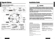
Connection with Upgrade options
Connecting devices shown below allows you to enjoy a wonderful world consisting of a wide
variety of pictures and sounds.
CY-V7100U
PHONES
P
a
n
a
s
o
n
i
c
Camcorder
Headrest Monitor:
CY-V7100U, etc.
Rear View
Camera
INTELLIGENT SYSTEM
BS G-CODE
POWER
VCR
Refer to
“Connection with
VCR or
Camcorder”
(a page 25).
Refer to “Connection with
Headrest Monitor” (a page 26)
Refer to
“Connection
with Rear
View Camera”
(a page 27)
CD Changer: CX-DP880U
Note: Two CD changers can be connected at
once by incorporating with CA-CD55 (option).
(a page 24).
S
O
U
R
C
E
S
EL
V
O
L
SOURCE
1
2
3
4
D
R
C
O
M
P
P
O
S
I
S
PC
DIM
M
U
T
E
A
C
3
0
0
s
u
p
e
r b
rig
h
t m
u
lti-c
o
lo
r d
is
p
la
y
&
3
0
w
P
o
w
e
r A
m
p
lifie
r
fo
r
C
e
n
te
r
S
p
e
a
k
er
D
I
G
I
T
A
L
P
R
O
L
O
G
I
C
D
IGATAL SURROU
ND PROCESSO
R
POSITION
DIMMER
SPACE
P
W
R
Front Speakers: CJ-DVD177
Subwoofer:
CJ-SW38
External power
amplifier:
CY-M7052
Surround
Speakers:
CJ-SS162
Digital Surround
Processor: CY-AC300
Refer to “Connection with Digital
Surround Processor” (a page 28).
Refer to “Connection
with CD Changer”
(a page 23).
WARNING
❐ This installation information is designed for professional installers with knowledge of
automobile electrical safety systems and is not intended for non-technical, do-it-yourself
individuals. It does not contain instructions on the electrical installation and avoidance of
potential harm to air bag, anti-theft and ABS braking or other systems necessary to install
this product.
Any attempt to install this product in a motor vehicle by anyone other than a profes-
sional installer could cause damage to the electrical safety system and could result in
serious personal injury or death.
❐ If your car is equipped with air bag and/or anti-theft systems, specific procedures may
be required for connection and disconnection of the battery to install this product.
Before attempting installation of this electronic component against the manufacturer's
recommendation, you must contact your car dealer or manufacturer to determine the
required procedure and strictly follow their instructions.
FAILURE TO FOLLOW THE PROCEDURE MAY RESULT IN THE UNINTENDED DEPLOY-
MENT OF AIR BAGS OR ACTIVATION OF THE ANTI-THEFT SYSTEM RESULTING IN DAM-
AGE TO THE VEHICLE AND PERSONAL INJURY OR DEATH.
❏ Overview
This product should be installed by a professional.
However, should you decide to install the product against
the manufacturer's recommendation, these operating
Instructions do not contain electrical installation instruc-
tions. You must contact your car dealer or manufacturer
for electrical connection instructions to avoid possible
damage to your electrical safety systems and resulting
injury or death. (Please refer to the “WARNING” state-
ment above).
Your next step is to decide where to install the unit. The
instructions in these pages will guide you through the
remaining steps:
¡Identify and label the car wires.
¡Connect the car wires to the wires of the power connec-
tor.
¡Install the unit.
¡Check the operation of the unit.
If you encounter problems, please consult your nearest
professional installer.
Warning: This unit operates with a 12 V DC negative
ground auto battery system only. Do not attempt to use
it with any other system. Doing so could cause serious
damage.
Before you begin installation, look for the following items
which are packed with your unit.
¡Warranty Card …… Fill this out promptly.
¡Panasonic Servicenter for Service Directory ……
Keep for future reference in case the product needs ser-
vicing.
¡Installation Hardware …… Needed for installation.

8 9
CQ-VD7500UCQ-VD7500U
3
E
N
G
L
I
S
H
4
E
N
G
L
I
S
H
Installation Guide (continued)
❏ Before Installation
Warning
¡Do not install the monitor in a location which
obstructs driving, visibility or which is prohibited
by applicable laws and regulations. If the monitor
is installed in a location which obstructs forward vis-
ibility or operation of the air bag or other safety
equipment or which interferes with operation of the
car, it may cause an accident.
¡Never use bolts or nuts from the car's safety devices
for installation. If bolts or nuts from the steering
wheel, brakes or other safety devices are used for
installation of the monitor, it may cause an accident.
¡Attach the wires correctly. If the wiring is not cor-
rectly performed, it may cause a fire or an accident.
In particular, be sure to run and secure the lead wire
so that it does not get tangled with a screw or the
moving portion of a seat rail.
¡Use with 12 V DC negative ground car. This unit is
only for use with a 12 V DC negative ground car. It
cannot be used in large trucks or diesel cars which
are 24 V DC cars. If it is used in the wrong type of
car, it may cause a fire or an accident.
❏ Required Tools
You’ll need a screwdriver and the following:
12 V DC
Test Bulb
Electrical
Tape
Side-Cut
Pliers
Cautions:
¡Use the specified fuse. Be sure to always use the
specified fuse. If a fuse other than the specified fuse
is used, it may cause a fire or an accident.
¡Do not damage the cord by pinching or pulling it.
Do not pull or damage the cord. If the cord is not
treated properly, it will short out or be severed and
may cause a fire or an accident.
❏ Dashboard Specifications
❏ Identify All Leads
The first step in installation is to identify all the car wires
you’ll use when hooking up your LCD monitor.
As you identify each wire, we suggest that you label it
using masking tape and a permanent marker. This will help
avoid confusion when making connections later.
Note: Do not connect the power connector to the display
unit until you have made all connections. If there are no
plastic caps on the hooking wires, insulate all exposed
leads with electrical tape until you are ready to use them.
Identify the leads in the following order.
Power Lead
If your car has a radio or is pre-wired for one:
Cut the connector wires one at a time from the plug (leav-
ing the leads as long as possible) so that you can work
with individual leads. Turn the ignition on to the accessory
position, and ground one lead of the test bulb to the chas-
sis.
Touch the other lead of the test bulb to each of the exposed
wires from the cut radio connector plug. Touch one wire at a
time until you find the outlet that causes the test bulb to
light.
Now turn the ignition off and then on. If the bulb also turns
off and on, that outlet is the car power lead.
If your car is not wired for an audio unit:
Go to the fuse block and find the fuse port for radio
(RADIO) accessory (ACC) or ignition (IGN).
Battery Lead
If your stereo unit has a yellow lead, you will need to
locate the car's battery lead. Otherwise you may ignore
this procedure. (The yellow battery lead provides continu-
THICKNESS
MIN. 3/16” (4.75 mm)
MAX. 7/32” (5.56 mm)
2-3/32” (53 mm)
7-5/32” (182 mm)
❏ Installation Hardware
(For Installation)
❏ Installation Hardware
(For
Wiring)
Notes:
¡The number in parenthesis underneath each accessory
part name is the part number for maintenance and ser-
vice.
¡Accessories and their parts numbers are subject to
modification without prior notice due to improvements.
¡Trim Plate q and Mounting Collar w are mounted on
the main unit at shipment.
Q'tyDiagramItemNo. Q'tyDiagramItemNo.
Trim Plate
<YEP9FZ2739>
q
1
Mounting Bracket
<YEFG021010A>
!6
2
Base Bracket
<YEFG012424>
!7
2
Mounting Collar
<YEFG012694>
w
1
Mounting Spring
<YEFX0052714>
e
2
Rear Support Strap
<YEFG04019>
<YEP9BS1206>
u
1
Display Unit/Hide-away Unit
Connecting Cord
<YEAJ071659>
@5
1
Power Connector
(for hide-away unit)
<YEAJ012003>
@6
1
Ground Lead
<YEAJ09271>
@7
1
Radio Antenna Extension
Cord
<YEAA09141>
@8
1
TV Antenna
<YEAA12692A (R)/12693A (L)>
@9
1 set
Round Head Screw
(5 mmø x 6 mm)
i
2
Flat-Head Screw
(5 mmø x 6 mm)
o
4
Round Head Screw
(4 mmø x 3 mm)
!0
4
<YEAJ012002>
Power Connector
(for display unit)
@2
1
Reverse Extension Cord
(for rear view camera)
@3
1
Clip Connector
@4
1
<YEP9BS1194>
Round Head Screw
(5 mmø x 8 mm)
!3
4
Tapping Screw
(6 mmø x 20 mm)
!4
4
Hex. Nut (5 mmø)
!5
4
Q'tyDiagramItemNo.
<YEP9FZ2714>
Mounting Bolt (5 mmø)
r
1
Tapping Screw (5 mmø x 16
mm)
(for rear of the unit)
t
1
Hex. Nut (5 mmø)
(for rear of the unit)
y
1
<YEP9FZ2761>
Spacer
!1
2
Double-Faced Adhesive Tape
(for spacer)
!2
1
set
<YEP9FZ3042>
Double-Faced Adhesive Tape
(for hide-away unit)
!8
2
Velcro Tape
!9
2
<YEP9FZ3041>
Antenna Clamp
@0
4
Cord Clamp (for antenna)
@1
4
Product specificaties
| Merk: | Panasonic |
| Categorie: | Autoradio |
| Model: | CQ-VD7500U |
Heb je hulp nodig?
Als je hulp nodig hebt met Panasonic CQ-VD7500U stel dan hieronder een vraag en andere gebruikers zullen je antwoorden
Handleiding Autoradio Panasonic
2 April 2025

28 Maart 2025
26 Maart 2025

26 Maart 2025

26 Maart 2025
26 Maart 2025
26 Maart 2025
26 Maart 2025
26 Maart 2025
26 Maart 2025
Handleiding Autoradio
- Twister
- Trevi
- Sevic
- Xblitz
- Voxx
- Krüger And Matz
- Axton
- Brigmton
- Alpine
- Naxa
- Pyle
- Blaupunkt
- Tamashi
- Overmax
- Dual
Nieuwste handleidingen voor Autoradio

12 September 2025

11 Augustus 2025

22 Juli 2025

21 Juli 2025

15 Juli 2025

14 Juli 2025
14 Juli 2025

14 Juli 2025

5 Juli 2025

4 Juli 2025