Optex FTN-AM Handleiding
Optex Niet gecategoriseerd FTN-AM
Bekijk gratis de handleiding van Optex FTN-AM (8 pagina’s), behorend tot de categorie Niet gecategoriseerd. Deze gids werd als nuttig beoordeeld door 44 mensen en kreeg gemiddeld 4.3 sterren uit 5 reviews. Heb je een vraag over Optex FTN-AM of wil je andere gebruikers van dit product iets vragen? Stel een vraag
Pagina 1/8
< CONTENTS >
< FEATURES >
Multilingual instructions
Visit to the Web site to find
valious language versions.
https://navi.optex.net/manual/08697/
EN-1
EN
No.59-2263-2 2207-16
INSTALLATION INSTRUCTIONS
fit
fit
FTN-STStandard model with 2 PIRs
FTN-AMFTN-ST with anti-masking
Compact outdoor
detector
Compact outdoor
detector
series
series
WIRED MODEL
•Compact design
•190° adjustable bracket
•Intelligent AND logic
•Digital anti-masking (AM model)
•Wall tamper (option)
1 INTRODUCTION
1-1 BEFORE INSTALLATION......................................1
1-2 PARTS IDENTIFICATION......................................2
1-3 DETECTION AREA................................................2
2 INSTALLATION
2-1 INSTALLATION......................................................3
3 WALK TEST
3-1 WALK TEST...........................................................5
4 DIP SWITCH SETTING
4-1 LED........................................................................5
4-2 ALARM OUTPUT...................................................5
4-3 PIR SENSITIVITY..................................................5
4-4 ANTI-MASKING......................................................6
5 OTHERS
5-1 WALL TAMPER (OPTION) CONNECTION...........6
5-2 EXAMPLE OF EOL WIRING..................................7
5-3 LED LIGHT PATTERN...........................................7
6 SPECIFICATIONS
6-1 SPECIFICATIONS..................................................8
6-2 DIMENSIONS.........................................................8
The check
mark indicates recommendation.
The nix
sign indicates prohibition.
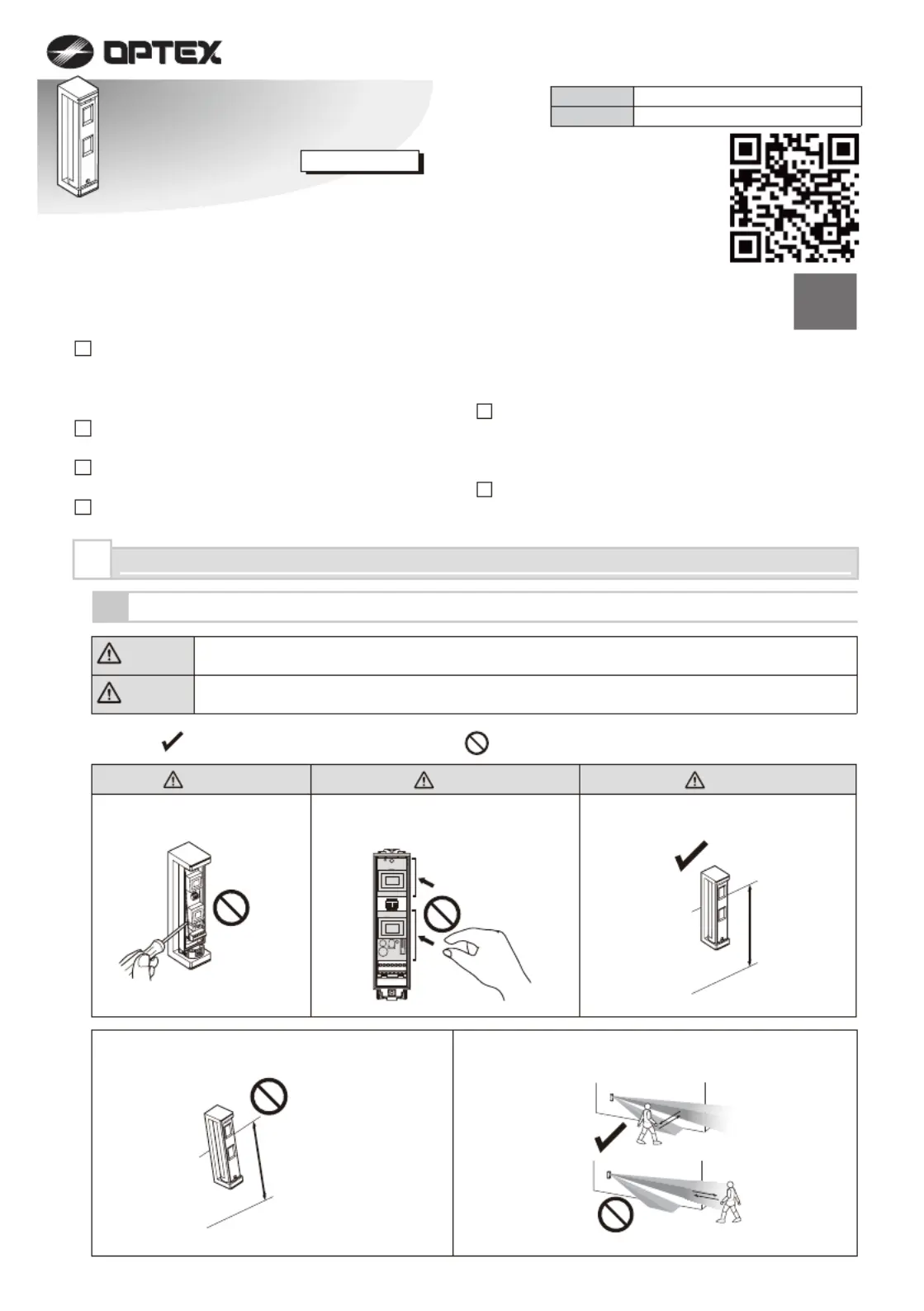
Warning
Caution
Failure to follow the instructions provided with this indication and improper handling may cause
death or serious injury.
Failure to follow the instructions provided with this indication and improper handling may cause
injury and/or property damage.
Warning
CautionCaution
Do not remove the PCB.
ON
234
1
0.8 to 1.2 m
(2.6 to 3.9 ft.)
Parallel
Mounting height.
Tilt
Keep the detector parallel to the ground.
Consider the direction of the intruder,
for the setting of the detection area.
Do not touch the PCB except for the
DIP switch.
1
INTRODUCTION
1-1
BEFORE INSTALLATION
Product specificaties
| Merk: | Optex |
| Categorie: | Niet gecategoriseerd |
| Model: | FTN-AM |
Heb je hulp nodig?
Als je hulp nodig hebt met Optex FTN-AM stel dan hieronder een vraag en andere gebruikers zullen je antwoorden
Handleiding Niet gecategoriseerd Optex

22 December 2025
5 Juli 2025
16 Juni 2025
27 Januari 2025
21 December 2024
5 December 2024
5 December 2024
5 December 2024
5 December 2024
5 December 2024
Handleiding Niet gecategoriseerd
Nieuwste handleidingen voor Niet gecategoriseerd
23 Juli 2026
23 Juli 2026
23 Juli 2026
22 Juli 2026
22 Juli 2026
22 Juli 2026
22 Juli 2026
22 Juli 2026
22 Juli 2026
21 Juli 2026