Optex SL-650QDP Handleiding
Optex Niet gecategoriseerd SL-650QDP
Bekijk gratis de handleiding van Optex SL-650QDP (10 pagina’s), behorend tot de categorie Niet gecategoriseerd. Deze gids werd als nuttig beoordeeld door 84 mensen en kreeg gemiddeld 4.8 sterren uit 3 reviews. Heb je een vraag over Optex SL-650QDP of wil je andere gebruikers van dit product iets vragen? Stel een vraag
Pagina 1/10
-1-
INSTALLATION INSTRUCTIONS
No.59-1881-3 131115UL
No.59-1881-3
PHOTOELECTRIC DETECTOR
• Quad high power beams
• Double modulated beam
• Smart design
- Slim body design
- Easy-to-see vivid interior color for optical alignment
- IP65*
1
waterproof structure
• 4 channel beam frequency selector
• Alignment level indicator
• Viewfinder with 2X magnification
• Various options (refer to page 20)
( HU-3*
1
, ABC-4*
1
, BC-4*
1
, CBR-4, PSC-4*
1
, BAU-4*
1
)
• UL/c-UL Listed
• Beam interruption adjustment function
• D.Q. circuit (environmental disqualification)
• Tamper function
• Beam power control selector
• Alarm memory
• Sound assist function
-
Optical alignment
- Beam reception status
- Walk test
[ SL-QDM only ]
• Auto Transmit Power Control (A.T.P.C*
2
) to optimize the beam power
• Integrated Alignment Status Communication (I.A.S.C*
2
) to
communicate the transmitter and receiver
• Re-transmitting circuit function
• Solar Battery Unit SBU-4*
1
(option)
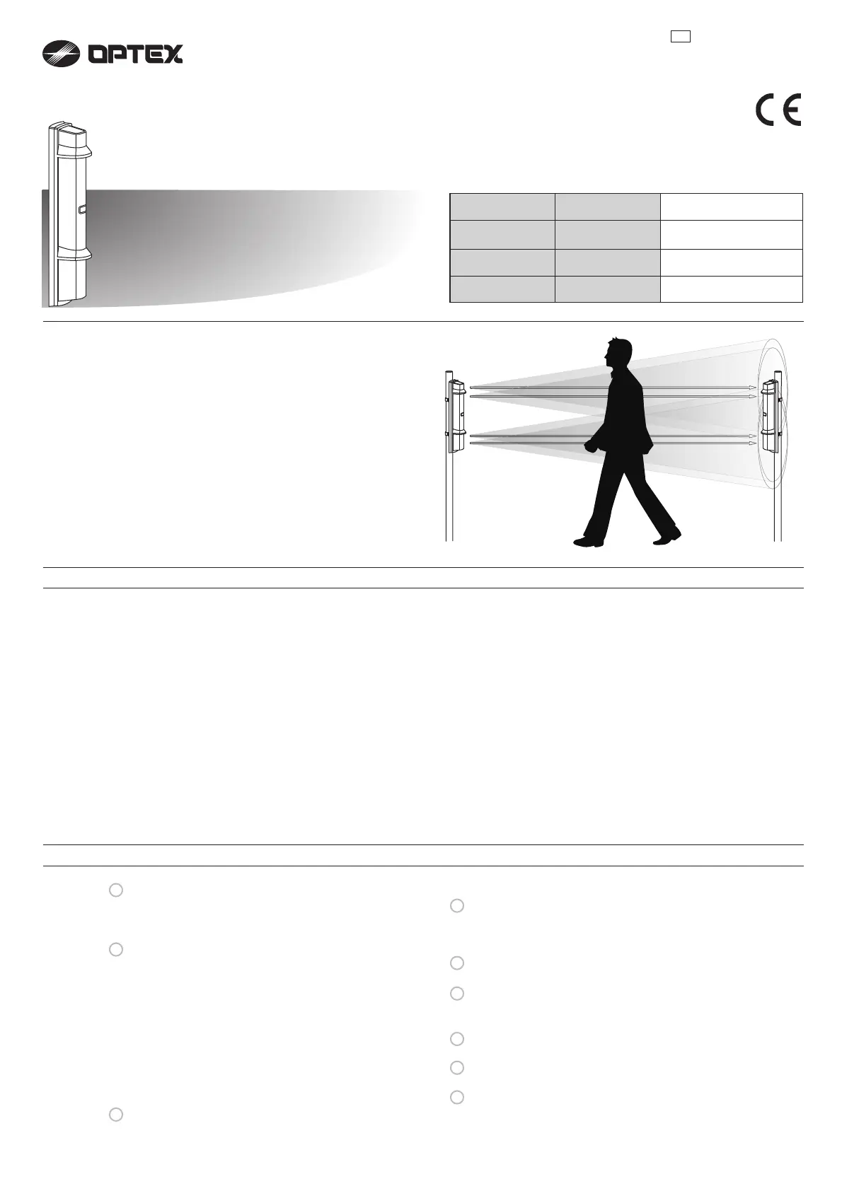
PHOTOELECTRIC DETECTOR
A photoelectric detector consists of an infrared light
source that generates IR(Infrared) beams, and an IR
receiver that detects the IR beams. The transmitter
and receiver are installed on opposite sides of the
area to be monitored. The receiver detects when the
IR beams are physically interrupted by an intruder,
and sends an alarm signal to be a control panel.
FEATURES
INTRODUCTION
1-1 BEFORE YOUR OPERATION.......................2
1-2 PRECAUTIONS
.......................................................
2
1-3 PARTS IDENTIFICATION
.....................................
3
INSTALLATION
2-1 SEPARATING.................................................4
2-2 WIRING..........................................................4
2-3 TERMINAL.....................................................5
2-4 WIRING DIAGRAM........................................5
2-5 WIRING DISTANCE BETWEEN POWER
SUPPLY AND DETECTOR............................6
2-6 WALL MOUNTING.........................................6
2-7 POLE MOUNTING.........................................8
2-8 MOUNTING IN THE BEAM TOWER..............9
2-9
INSTALLATION EXAMPLE AT PARTICULAR CASE
...9
FUNCTION SETTING
3-1 DIP SWITCH.................................................10
3-2 BEAM POWER CONTROL SELECTOR.......10
1
2
3
4
6
7
8
9
CONTENTS
3-3 FUNCTION....................................................11
OPTICAL ALIGNMENT
4-1 OPTICAL ALIGNMENT FOR UPPER AND
LOWER BEAM..............................................15
4-2 OPERATION CHECK....................................17
TROUBLESHOOTING
5-1 TROUBLESHOOTING..................................17
OPTIONAL SETTING
6-1 HEATER UNIT HU-3 (OPTION)....................18
6-2 SOLAR BATTERY UNIT SBU-4 (OPTION)...18
DIMENSIONS
7-1 DIMENSIONS...............................................19
SPECIFICATIONS
8-1 SPECIFICATIONS.........................................19
OPTIONS
9-1 OPTIONS......................................................20
Detection range
SL-200QDM
SL-350QDM
SL-650QDM
SL-200QDP
SL-350QDP
SL-650QDP
AdvancedStandard
5
Transmitter
Receiver
Smart Line series
Smart Line series
™
™
60m/200ft.
100m/350ft.
200m/650ft.
*1 not evaluated by UL
*2 not require any additional tool
Product specificaties
| Merk: | Optex |
| Categorie: | Niet gecategoriseerd |
| Model: | SL-650QDP |
| Kleur van het product: | Zwart |
| Gewicht: | 2400 g |
| Breedte: | 79 mm |
| Diepte: | 96 mm |
| Hoogte: | 448 mm |
| Internationale veiligheidscode (IP): | IP65 |
| Omgevingstemperatuur (min): | -35 °C |
| Omgevingstemperatuur (max): | 60 °C |
| Stroom (max.): | 0.2 A |
| Zendbereik: | 200 - 2000 m |
Heb je hulp nodig?
Als je hulp nodig hebt met Optex SL-650QDP stel dan hieronder een vraag en andere gebruikers zullen je antwoorden
Handleiding Niet gecategoriseerd Optex

22 December 2025
5 Juli 2025
16 Juni 2025
27 Januari 2025
21 December 2024
5 December 2024
5 December 2024
5 December 2024
5 December 2024
5 December 2024
Handleiding Niet gecategoriseerd
Nieuwste handleidingen voor Niet gecategoriseerd
2 Augustus 2026
2 Augustus 2026
2 Augustus 2026
1 Augustus 2026
31 Juli 2026
31 Juli 2026
31 Juli 2026
31 Juli 2026
31 Juli 2026
31 Juli 2026