Noctua NH-L9x65 chromax.black Handleiding
Noctua Hardwarekoeling NH-L9x65 chromax.black
Bekijk gratis de handleiding van Noctua NH-L9x65 chromax.black (2 pagina’s), behorend tot de categorie Hardwarekoeling. Deze gids werd als nuttig beoordeeld door 19 mensen en kreeg gemiddeld 5.0 sterren uit 8 reviews. Heb je een vraag over Noctua NH-L9x65 chromax.black of wil je andere gebruikers van dit product iets vragen? Stel een vraag
Pagina 1/2
This manual will guide you through the installation
process of the SecuFirm2™ mounting system step
by step.
Prior to installing the cooler, please consult
the compatibility centre on our website (ncc.noctua.at)
and verify that the cooler is fully compatible with your
motherboard, CPU, RAM and case. Please also make
sure that there are no compatibility issues with any other
components.
Double check that the heatsink and fan clips do not
make contact with the VGA card, other PCIe cards,
motherboard heatsinks or any other components.
Noctua cannot be held responsible for any damage or
losses caused by compatibility issues.
Should you encounter any difculties, please
check the FAQs on our website (faqs.noctua.at)
and don’t hesitate to contact our support team at
support@noctua.at.
Multilingual versions of this manual are available on our
website: www.noctua.at/manuals
Dear customer,
Thank you very much for choosing the Noctua
NH-L9x65 chromax.black.
The NH-L9x65 chromax.black is an all-black version
of Noctua’s award-winning NH-L9x65 premium-
quality quiet CPU cooler.
I’m condent that you will be able to sense some of
the research, attention and care we’ve put into making
this cooler.
Enjoy your Noctua NH-L9x65 chromax.black!
Yours sincerely,
Roland Mossig, Noctua CEO
Scan this code to
display multilingual
manuals on your
phone.
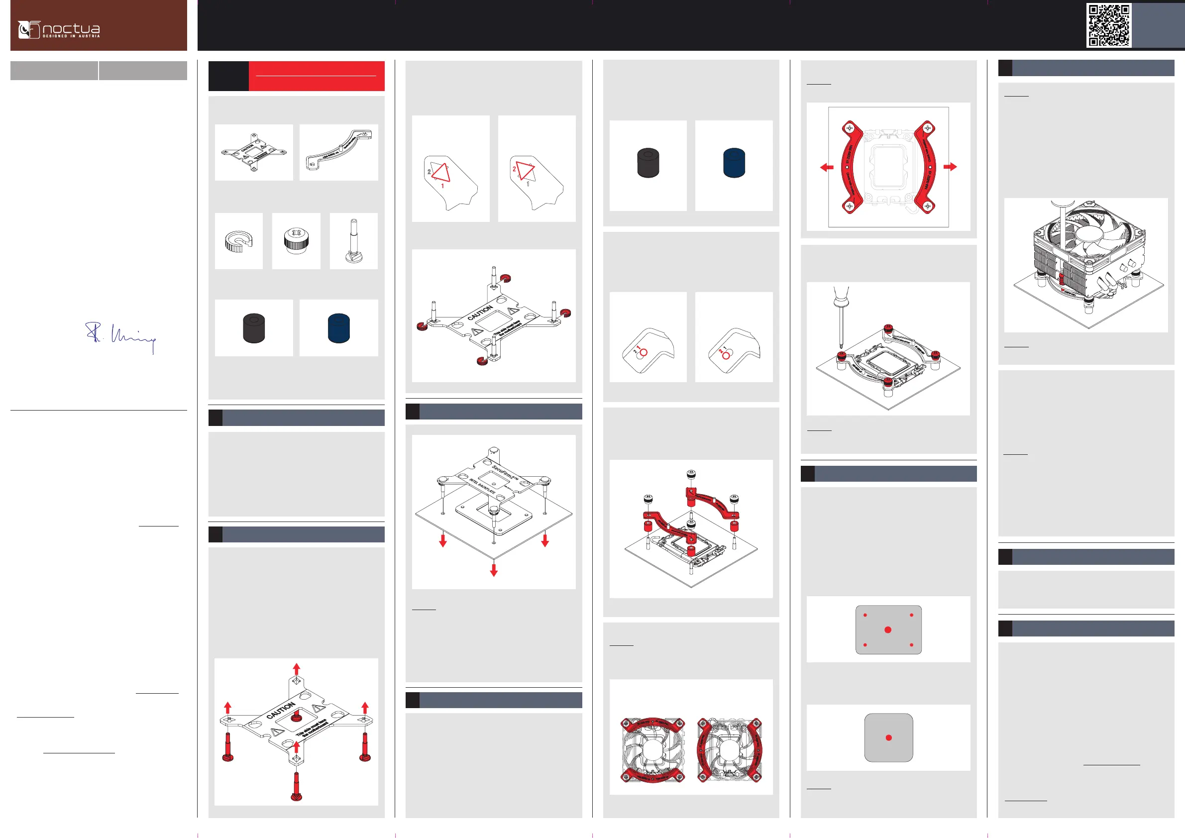
NOCTUA NH-L9x65 chromax.black
INSTALLATION MANUAL
INTELAMD
Transporting your system Fastening the heatsink to the CPU6
Required mounting parts:
If you would like to use the cooler on an assembled
system and your case does not have a cut-out at
the rear side of the motherboard tray, you must rst
remove the motherboard from the case in order to be
able to install the supplied backplate.
Removing the motherboard1
Setting up the backplate2
First, identify the side of the backplate that should face
the motherboard (marked with caution signs). Then
choose the appropriate hole spacing for your socket
and insert the four bolts into the backplate from
the opposite side (marked with model name,
SecuFirm2™ branding and numbers for hole spacing)
at the appropriate position.
4x NM-IPS1
black plastic spacers for
LGA1200/115x
4x NM-IPS3
blue plastic spacers for
LGA1851/1700
4x NM-IBT5
bolts
4x NM-ICS1
clip-on spacers
4x NM-STS1
thumb screws
2x NM-IMB2
mounting bars
1x NM-IBP4
backplate
LGA1851, LGA1700,
LGA1200 & LGA115x
Attaching the backplate3
Installing the mounting bars4
Put the plastic spacers onto the bolts of the backplate,
then add the mounting bars.
Use hole position 1 for LGA1200/LGA115x (LGA1150,
LGA1151, LGA1155, LGA1156) and hole position 2
for LGA1851/LGA1700:
Caution: Choose the alignment of the mounting bars
according to the desired nal orientation of the cooler.
Position 1:
LGA1200/115x
Position 2:
LGA1851/1700
Applying the thermal paste5
If there are residual traces of thermal paste or thermal
pads on your CPU, please clean them off rst. Then
apply the supplied NT-H1 thermal paste onto the CPU
as shown in the following images.
For LGA1851/LGA1700, apply 5 small dots; 4 dots
with ~2mm diameter near the corners plus 1 dot with
3-4mm diameter in the centre:
Caution: Applying too much thermal paste will lower
heat conductivity and cooling performance!
For LGA1200/LGA115x (LGA1150, LGA1151, LGA1155,
LGA1156) apply a single 4-5mm dot in the centre:
NM-IPS3 (blue)
LGA1851/1700
NM-IPS1 (black)
LGA1200/115x
Use the black NM-IPS1 plastic spacers for LGA1200/
LGA115x (LGA1150, LGA1151, LGA1155, LGA1156)
and the blue NM-IPS3 spacers for LGA1851/LGA1700.
Caution: Make sure that the curved sides of the
mounting bars are pointing outwards.
Fix the mounting bars using the four NM-STS1 thumb
screws.
Caution: Gently tighten the screws until they stop, but do
not use excessive force (max. torque 0.6 Nm).
Fix the bolts using the NM-ICS1 clip-on spacers.
Caution: The supplied backplate will install over the
motherboard’s stock backplate, so the motherboard’s
stock backplate must not be taken off.
Place the backplate on the rear side of the motherboard
so that the bolts protrude through the mounting holes.
Please rst choose the correct set of plastic spacers
and the correct set of holes on the mounting bars
according to whether you are using an LGA1200/
LGA115x (LGA1150, LGA1151, LGA1155, LGA1156)
or an LGA1851/LGA1700 socket motherboard.
Position 1:
LGA1200/115x
Position 2:
LGA1851/1700
Use hole position 1 for LGA1200/LGA115x (LGA1150,
LGA1151, LGA1155, LGA1156) and hole position 2
for LGA1851/LGA1700:
INTEL
Caution: Please rst take off the protection cover at the
bottom side of the heatsink.
Then put the heatsink onto the CPU and screw it to the
screw threads of the mounting bars. Perform 2-3 turns
on each screw, then repeat until both are fully tightened.
Note that you can reach through the blades of the fan
using the supplied screw driver. There is thus no need to
take off the fan for installation.
Caution: Gently tighten the screws until they stop, but do
not use excessive force (max. torque 0.6 Nm).
Connect the fan to the motherboard’s CPU fan header.
Depending on your CPU and the temperature inside
the case, you may interconnect the supplied NA-RC7
Low-Noise Adaptor (L.N.A.) in order to further reduce the
fans’ operating noise.
Caution: When using the L.N.A., check the
temperature of your CPU using appropriate software
(e.g. the respective applications of your motherboard
manufacturer), in order to evade automatic throttling
of the CPU due to the increased temperature. If the
cooling performance is insufcient, please increase
case ventilation or remove the L.N.A.
Due to the low weight of the cooler, it is not necessary
to take it off for transport.
Even with high-grade products and strict quality control,
the possibility of defects cannot be eliminated entirely.
Therefore, we aim at providing the highest possible level
of reliability and convenience by offering a warranty
period of 6 years and direct, fast and straightforward
RMA service.
Should you encounter any problems with your
NH-L9x65 chromax.black, please don’t hesitate to
contact our support team ([email protected]).
Please also consult the FAQ section on our website:
faqs.noctua.at
Transporting your system!
Warranty, support and FAQs!
Orientation 1
(default orientation)
Orientation 2
Product specificaties
| Merk: | Noctua |
| Categorie: | Hardwarekoeling |
| Model: | NH-L9x65 chromax.black |
| Kleur van het product: | Zwart |
| Gewicht: | 413 g |
| Breedte: | 95 mm |
| Diepte: | 95 mm |
| Hoogte: | 65 mm |
| Soort: | Koelplaat/radiatoren |
| Geluidsniveau (hoge snelheid: | 23.6 dB |
| Type verpakking: | Doos |
| Netvoeding: | 2.52 W |
| Materiaal: | Aluminium, Copper, Nickel |
| Luchtstroom: | 57.5 m³/uur |
| Aantal per verpakking: | 1 stuk(s) |
| Aantal ventilatoren: | 1 ventilator(en) |
| Spanning: | 12 V |
| Rotatiesnelheid ( max): | 2500 RPM |
| Mean time between failures (MTBF): | 150000 uur |
| Rotatiesnelheid ( min): | 600 RPM |
| Geschikte locatie: | Processor |
| Basis plaat materiaal: | Koper |
| Geluidsniveau ventilatie (max): | 23.6 dB |
| Ventilator diameter: | 95 mm |
| Aantal ventilatorbladen: | 9 |
| Fan voltage: | 12 V |
| Supported processor sockets: | Intel LGA1851, LGA 1150 (Socket H3), LGA 1151 (Socket H4), LGA 1155 (Socket H2), LGA 1156 (Socket H), LGA 1200 (Socket H5), LGA 1700, LGA 1851, Socket AM4, Socket AM5 |
| Pulsbreedtemodulatie-ondersteuning: | Ja |
| Materiaal vinnen: | Aluminium |
| Aantal warmte pijpen: | 4 |
| Maten ventilator (b x d x h): | 92 x 14 x 92 mm |
| Garantieperiode: | 6 jaar |
| Radiator materiaal: | Aluminium |
| Radiator breedte: | 95 mm |
| Radiator diepte: | 95 mm |
| Radiator hoogte: | 51 mm |
| Inclusief thermisch pad: | Ja |
Heb je hulp nodig?
Als je hulp nodig hebt met Noctua NH-L9x65 chromax.black stel dan hieronder een vraag en andere gebruikers zullen je antwoorden
Handleiding Hardwarekoeling Noctua

14 Juli 2025
14 April 2025
14 April 2025
14 April 2025
14 April 2025
9 April 2025
20 November 2024
22 Oktober 2024
22 Oktober 2024
25 September 2024
Handleiding Hardwarekoeling
Nieuwste handleidingen voor Hardwarekoeling
26 Mei 2026
19 Mei 2026
18 Mei 2026
14 Mei 2026
14 Mei 2026
12 Mei 2026
10 Mei 2026
8 Mei 2026