Microchip SY88822V Handleiding
Microchip Niet gecategoriseerd SY88822V
Bekijk gratis de handleiding van Microchip SY88822V (6 pagina’s), behorend tot de categorie Niet gecategoriseerd. Deze gids werd als nuttig beoordeeld door 91 mensen en kreeg gemiddeld 4.1 sterren uit 7 reviews. Heb je een vraag over Microchip SY88822V of wil je andere gebruikers van dit product iets vragen? Stel een vraag
Pagina 1/6
1
SY88822V Evaluation Board
Micrel
M9999-040804
[email protected] or (408) 955-1690
DESCRIPTION
The SY88822V features:
■Single 3.3V or 5V power supply
■Up to 155Mbps operation
■Modulation current to 30mA
■PECL output enable
■Differential PECL inputs
■Available in a tiny 10-pin (3mm
××
××
×3mm) MSOP
The SY88822V evaluation board features:
■User adjustable potentiometer to adjust
modulation current
■50Ω equivalent input network termination
■AC-coupled I/O with SMA connectors
FUNCTIONAL FEATURES
5V/3.3V 155Mbps
LASER DIODE DRIVER
WITH OUTPUT ENABLE
SY88822V
EVALUATION BOARD
AVAILABLE MEASUREMENTS
■Frequency performance
■Output eye pattern generation
■Mask testing
■Jitter
■Output rise/fall time
■BER testing
Rev.: AAmendment: /0
Issue Date:April 8, 2004
The SY88822V is a high-speed current switch for driving
a semiconductor laser diode in optical transmission
applications. The modulation current (I
OUT
) is controlled by
the current (I
RSET
) through the external resistor R
SET
. The
output OUT is HIGH and no current flows through OUT
when output enable is HIGH.
The device incorporates complementary open-collector
outputs with a 30mA maximum current driving capability.
The external resistor R
EXT
must be placed between /OUT
and V
CC
to dissipate the worst case power. R
SER
is
recommended to compensate for laser diode matching
issues. Pin 9 and pin 10 should be connected to achieve
better performance.
This manual provides information on the SY88822V
evaluation board. It should be used in conjunction with the
SY88822V datasheet, which contains full specifications for
the SY88822V.
The SY88822V evaluation board enables fast and
thorough electrical evaluation of the SY88822V 155Mbps
laser diode driver with output enable. The board is an easy-
to-use, single-layer, high-speed microstrip design. It is
designed to be driven by a high-speed 155Mbps pattern
generator and provides on-board 50Ω equivalent
terminations for the generator’s outputs. The input
termination network also provides the SY88822V's required
input bias of V
CC
–1.3V.
The board is intended to be terminated to a 50Ω scope
and provides for simple user adjustability of the modulation
current through the adjustment of an on-board potentiometer.
With the amplitude of the voltage waveform displayed on
the scope, the user can verify that the desired modulation
current is obtained through the equation:I
mod
(mA) =
V
amp
(V)/ 0.025kΩ.
All data sheets and support documentation can be found
on Micrel’s web site at www.micrel.com.
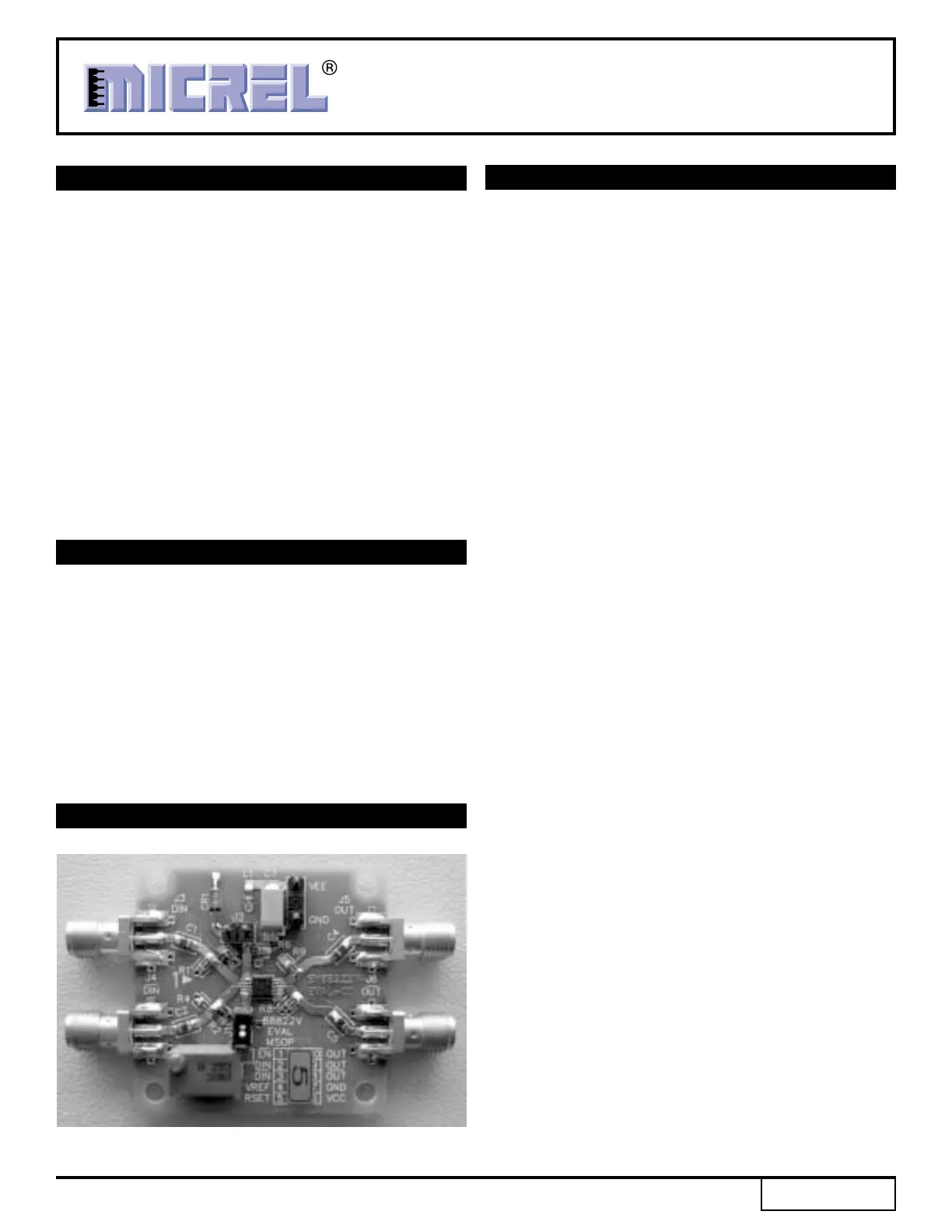
EVALUATION BOARD
Figure 1.SY88822V Evaluation Board
Product specificaties
| Merk: | Microchip |
| Categorie: | Niet gecategoriseerd |
| Model: | SY88822V |
Heb je hulp nodig?
Als je hulp nodig hebt met Microchip SY88822V stel dan hieronder een vraag en andere gebruikers zullen je antwoorden
Handleiding Niet gecategoriseerd Microchip

2 Februari 2026
26 Januari 2026
13 Januari 2026
12 Januari 2026
12 Januari 2026
12 Januari 2026
12 Januari 2026
12 Januari 2026
6 December 2025
5 December 2025
Handleiding Niet gecategoriseerd
Nieuwste handleidingen voor Niet gecategoriseerd
12 Juni 2026
12 Juni 2026
11 Juni 2026
11 Juni 2026
11 Juni 2026
11 Juni 2026
11 Juni 2026
11 Juni 2026
11 Juni 2026
11 Juni 2026