Microchip PIC16F737 Handleiding


Lees hieronder de đź“– handleiding in het Nederlandse voor Microchip PIC16F737 (18 pagina's) in de categorie Niet gecategoriseerd. Deze handleiding was nuttig voor 16 personen en werd door 2 gebruikers gemiddeld met 4.5 sterren beoordeeld

Pagina 1/18
© 2007 Microchip Technology Inc. DS51140N-page 1
CONTENTS
1.0 Introduction ......................................................... 1
2.0 MPLAB ICE 2000 System................................... 1
3.0 Emulator-Related Issues .................................... 2
4.0 Processor Modules ............................................. 2
5.0 Device Adapters ................................................. 4
6.0 Device Adapter Target Footprints ....................... 9
1.0 INTRODUCTION
The processor modules for MPLAB® ICE 2000 are
interchangeable personality modules that allow
MPLAB ICE 2000 to be reconfigured for emulation of
different PIC® microcontrollers (MCUs). This modular-
ity allows the emulation of many different devices with
the addition of a processor module and device adapter,
which provides a very cost effective multiprocessor
emulation system.
The device adapters for MPLAB ICE 2000 are inter-
changeable assemblies that allow the emulator system
to interface to a target application system. Device
adapters also have control logic that allows the target
application to provide a clock source and power to the
processor module. The device adapters support PIC
MCUs in DIP, SDIP and PLCC packages.
Transition sockets, used along with a device adapter,
provide a method of accommodating all PIC MCU
packages, including SOIC, SSOP, PQFP and TQFP
packages.
2.0 MPLAB ICE 2000 SYSTEM
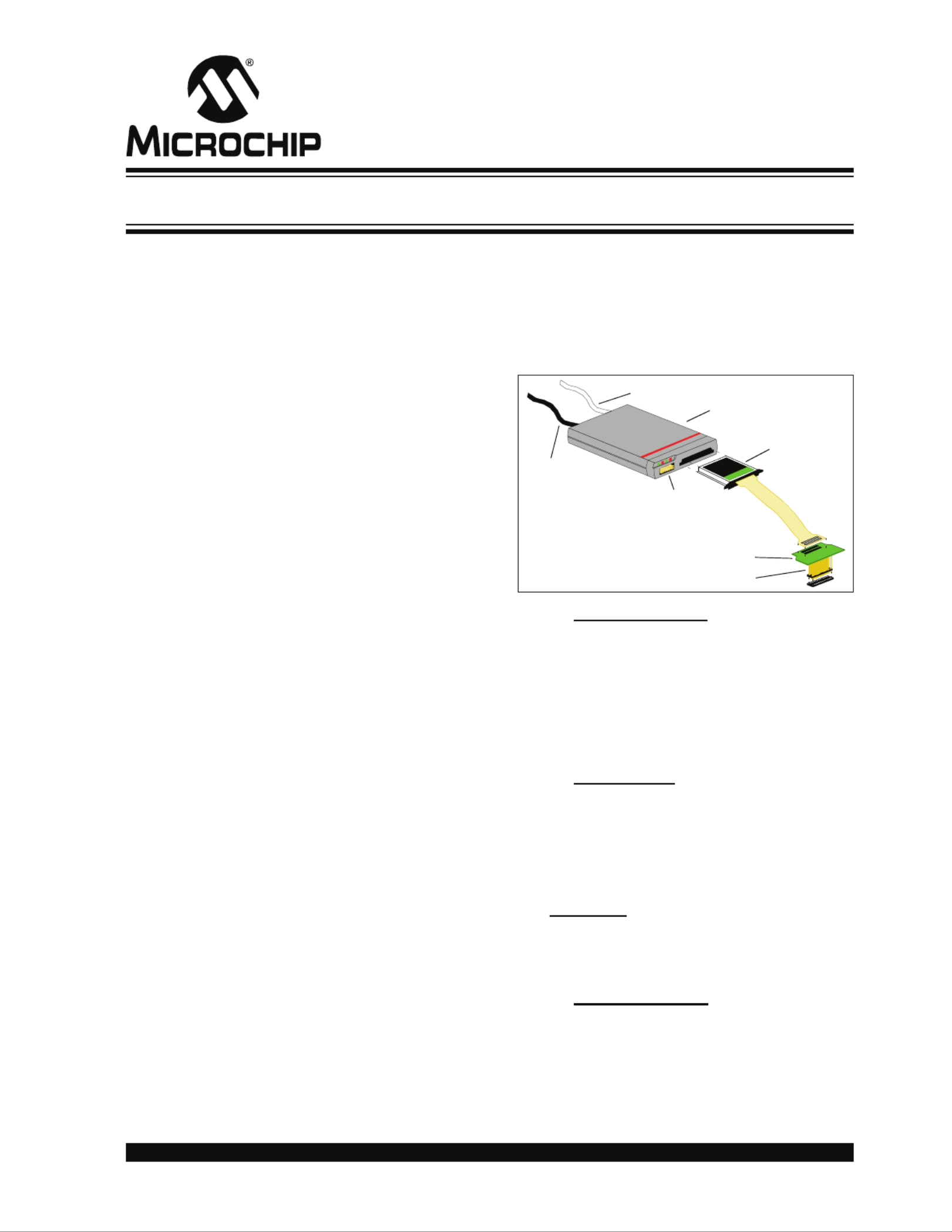
A brief overview of the different components of the
system is shown in the figure below. Each component
is discussed in the following subsections.
FIGURE 2-1: MPLAB® ICE 2000
EMULATOR SYSTEM
2.1 Host to Pod Cable
This is a standard parallel interface cable. MPLAB ICE
2000 is tested with a 6-foot cable. A longer cable may
work, but is not ensured. The cable connects to a par-
allel port on the PC. If a PC has a printer connected to
an LPT device, it is recommended that an additional
interface card be installed, rather than using a splitter
or an A/B switch.
2.2 Emulator Pod
The Emulator Pod contains emulator memory and
control logic. MPLAB ICE 2000 contains a main board
and an additional board for expanded trace memory
and complex control logic. There are no field service-
able parts in the pod. For more information on the pod,
see the MPLAB ICE 2000 on-line help file in MPLAB
IDE (Help>Topics) or the “MPLAB® ICE 2000
In-Circuit Emulator User’s Guide” (DS51488).
The MPLAB ICE 2000 processor module is inserted
into the pod for operation.
2.3 Processor Module
The processor module contains the emulator chip, logic
and low-voltage circuitry. There are no field-serviceable
parts mounted on the printed circuit board housed
within the processor module enclosure.
Communications Cable
Power Supply
Cable
Emulator Pod
Processor Module
with Cable
Logic Probe
Connector
Device Adapter
Transition Socket
Processor Module and Device Adapter Specification
MPLAB® ICE 2000
MPLAB® ICE 2000
DS51140N-page 2 © 2007 Microchip Technology Inc.
2.4 Flex Circuit Cable
Once the processor module is inserted into the
emulator pod, the flex circuit cable extends the
emulator system to the target application. This is a
custom cable that is attached inside the processor
module enclosure, and can be replaced in the field by
removing the end cap of the processor module
enclosure.
Please, DO NOT PULL on the flex circuit cable to
remove the processor module from the pod. Use the
fins of the processor module end cap to leverage the
module from the pod.
Emulator analog functions may not operate within the
performance specifications published in the device
data sheet due to parasitic capacitance (up to 120 pf)
of the flex cable.
2.5 Device Adapter
The device adapter provides a common interface for
the device being emulated. It is provided in standard
DIP and PLCC styles. The adapter also contains a spe-
cial device that provides an oscillator clock to accu-
rately emulate the oscillator characteristics of the PIC
MCU.
Due to components on the device adapter, which
require target power, the device adapter should be
removed from the flex circuit cable (see Figure 2-1)
when emulator power is being used and the processor
module is not connected to the target. This will
eliminate any loading effects on I/O pins.
2.6 Transition Socket
Transition Sockets are available in various styles to
allow a common device adapter to be connected to one
of the supported surface mount package styles. Transi-
tion sockets are available for various pin counts and
pitches for SOIC, QFP and other styles. For more infor-
mation on transition sockets, see the “MPLAB® ICE
2000/4000 Transition Socket Specification” (DS51194).
An emulator system consists of the following
components which can be ordered separately:
• An emulator pod (including the host-to-pod cable
and power supply)
• A processor module (including the flex circuit
cable)
• A device adapter
• An optional transition socket (for surface mount
emulation)
3.0 EMULATOR-RELATED ISSUES
General limitations that apply to the MPLAB ICE 2000
emulator may be found in the on-line help. Select
Help>Topics and then select “MPLAB ICE 2000” under
“Debuggers”.
Device-specific limitations can be found as above or by
selecting Debugger>Settings, clicking the Limitations
tab, and then clicking the Details button.
4.0 PROCESSOR MODULES
Processor modules are identified on the top of the
assembly (e.g., PCM18XA0). To determine which
processors are supported by a specific module, refer to
the file “Readme for MPLAB ICE 2000.txt” in the
MPLAB IDE installation directory or the latest “Product
Selector Guide” (DS00148), which can be found on the
Microchip web site at www.microchip.com.
A typical processor module contains a special bond-out
version of a PIC MCU, with device buffers to control
data flow and control logic. It provides the means of
configuring the MPLAB ICE 2000 emulator for a
specific PIC MCU family and handles low-voltage emu-
lation when needed.
4.1 Power
The operating voltage for most of the control logic and
buffering on the processor module is +5V and is
supplied by the emulator pod. Power to the emulator
processor and some of its surrounding buffers is user-
selectable, and can be powered by the emulator pod
(at +5V only) or the target application system (from
2.0V to 5.5V). This is software selectable and is
configurable through the MPLAB IDE software. At no
time will the emulator system directly power the target
application system. ALWAYS insert the processor
module into the emulator pod before applying power to
the pod.
When connecting to a target application system, there
may be a voltage level on the target application even
though power has not yet been applied to the target
application circuit. This is normal, and is due to current
leakage through VCC of the device adapter. The current
leakage will typically be less than 20 mA. However, if
the target application is using a voltage regulator, it
should be noted that some regulators require the use of
an external shunt diode between VIN and VOUT for
reverse-bias protection. Refer to the manufacturer’s
data sheets for additional information.
Note: When removing the processor module, DO
NOT PULL on the flex cable. Use the tabs
on the processor module or damage to the
flex cable may occur.
© 2007 Microchip Technology Inc. DS51140N-page 3
4.1.1 EMULATOR PROCESSOR POWER
SUPPLIED BY EMULATOR SYSTEM
If the emulator system is selected to power the emula-
tor processor in the processor module, the emulator
system can be operated without being connected to a
target application. If the system is being connected to a
target application, the power to the pod should be
applied before applying power to the target application.
The target application system’s VCC will experience a
small current load (10 mA typical) when the emulator
system is connected via a device adapter. This is
because the target system must always power the
clock chip in the processor module.
4.1.2 EMULATOR PROCESSOR POWER
SUPPLIED BY TARGET APPLICATION
SYSTEM
When the MPLAB IDE software is brought up, the
emulator system is first initialized with the emulator
system powering the emulator processor. The
“Processor Power Supplied by Target Board” option
may then be selected using the Power tab of the
Settings dialog (Debugger>Settings) to power the
processor module from the target board.
When operating from external power, the processor
module will typically represent a current load equivalent
to the device being emulated (according to its data
sheet) plus approximately 100 mA. Keep in mind that
the target application will affect the overall current load
of the processor module, dependent upon the load
placed upon the processor I/O.
When the processor power is supplied by the target
application system, an external clock (from the target
board) may also be provided. MPLAB IDE will not allow
use of an external clock without the use of external
power.
4.1.3 OPERATING VOLTAGE OF 4.6 TO 5.5
VOLTS
If the target application system’s operating voltage is
between 4.55V (±120 mV) and 5.5V, the processor
module will consider this a STANDARD VOLTAGE
condition. In this mode, the processor can run to its
highest rated speed (as indicated in its data sheet).
The recommended power-up sequence is:
1. Apply power to the PC host.
2. Apply power to the emulator pod and processor
module assembly.
3. Invoke MPLAB IDE.
4. Select Debugger > Settings and click the Power
tab. Configure system for “Processor Power
Supplied by Target Board”.
5. At the error message, apply power to the target
application circuit. Then acknowledge the error.
6. Issue a System Reset (from the debugger
menu) before proceeding.
4.1.4 OPERATING VOLTAGE OF 2.0 TO 4.6
VOLTS
If the target application system’s operating voltage is
between 2.0V and 4.55V (±120 mV), the processor
module will consider this a LOW VOLTAGE condition.
In this mode, the processor is limited to its rated speed
at a given voltage level (as indicated in its data sheet).
To minimize the amount of reverse current that the
target system is exposed to, the recommended
power-up sequence is:
1. Apply power to the PC host.
2. Apply power to the emulator pod and processor
module assembly.
3. Invoke MPLAB IDE.
4. Select Debugger > Settings and click the Power
tab. Configure system for “Processor Power
Supplied by Target Board”.
5. At the error message, apply power to the target
application circuit. Then acknowledge the error.
6. Issue a System Reset (from the debugger
menu) before proceeding.
7. Select Debugger > Settings and click the Power
tab. Verify that the dialog says “Low Voltage
Enabled.” Click Cancel to close the dialog.
4.2 Operating Frequency
The processor modules will support the maximum
frequency (except where noted in Section 3.0
“Emulator-Related Issues”) of the device under
emulation. The maximum frequency of a PIC MCU
device is significantly lower when the operating volt-
age is less than 4.5V.
The processor modules will support a minimum
frequency of 32 kHz. When operating at low
frequencies, response to the screen may be slow.
4.3 Clock Options
MPLAB ICE 2000 allows internal and external clocking.
When set to internal, the clock is supplied from the
internal programmable clock, located in the emulator
pod. When set to external, the oscillator on the target
application system will be utilized.
4.3.1 CLOCK SOURCE FROM EMULATOR
Refer to the MPLAB ICE 2000 on-line help file in
MPLAB IDE (Help>Topics) or the “MPLAB® ICE 2000
In-Circuit Emulator User’s Guide” (DS51488), “Using
the On-Board Clock”, for configuring MPLAB IDE to
supply the clock source.


Product specificaties

Merk: Microchip
Categorie: Niet gecategoriseerd
Model: PIC16F737

Heb je hulp nodig?

Als je hulp nodig hebt met Microchip PIC16F737 stel dan hieronder een vraag en andere gebruikers zullen je antwoorden


Handleiding Niet gecategoriseerd Microchip

Handleiding Niet gecategoriseerd

Nieuwste handleidingen voor Niet gecategoriseerd