Lasko R16610 Handleiding
Lasko
Ventilator
R16610
Bekijk gratis de handleiding van Lasko R16610 (4 pagina’s), behorend tot de categorie Ventilator. Deze gids werd als nuttig beoordeeld door 32 mensen en kreeg gemiddeld 4.2 sterren uit 16.5 reviews. Heb je een vraag over Lasko R16610 of wil je andere gebruikers van dit product iets vragen? Stel een vraag
Pagina 1/4

NEW 12/14 8 R16610ES
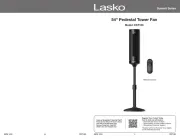
16" CLASSIC STAND FAN
MODEL R16610
IMPORTANT INSTRUCTIONS - OPERATING MANUAL
1R16610ES
MODELO R16610
This Fan is for residential use only.
It is not intended to be used in commercial, industrial or agricultural settings.
NEW 12/14
READ AND SAVE THESE INSTRUCTIONS
READ CAREFULLY BEFORE ATTEMPTING TO ASSEMBLE,
INSTALL, OPERATE OR MAINTAIN THE PRODUCT DESCRIBED.
PROTECT YOURSELF AND OTHERS BY OBSERVING ALL SAFETY
INFORMATION. FAILURE TO COMPLY WITH INSTRUCTIONS COULD
RESULT IN PERSONAL INJURY AND/OR PROPERTY DAMAGE!
Have a Question? Need a Part?
Please Do Not Return Product to Store!
Contact Lasko Customer Service:
1-800-233-0268 Monday-Friday 8AM - 5PM EST.
REPARACIONES: Para cualquier reparación, que no sea de mantenimiento general por parte del usuario, por favor contacte a nuestro
equipo de Servicio al Cliente al (800) 233-0268 de Lunes a Viernes de 8 a.m. a 5 p.m
ALMACENAMIENTO: Almacene el Ventilador con estas instrucciones, en la caja original en un lugar fresco y seco.
DISPOSICIÓN: Los materiales de empaque de cartón corrugado son reciclables. Para desechar este producto de manera
ecológicamente responsable, comuníquese con su proveedor de servicio de desechos local o visite www.1800recycling.com®.
CONSEJOS PARA SOLUCIONAR PROBLEMAS
Si su Ventilador falla al operar, ver abajo una lista de causas y soluciones probables:
1. Esté seguro que la cuerda del poder se tapa en un trabajar salida eléctrica.
SERVICIO AL CLIENTE:
Línea gratuita (800) 233-0268. Correo electrónico: producthelp@laskoproducts.com
Nuestro equipo de Servicio al Cliente está disponible para ayudarle con preguntas sobre productos, ubicaciones de los centros
de reparación y repuestos. Se puede comunicar con nuestro equipo de Servicio al Cliente de lunes a viernes, de 8 a.m. a 5 p.m.
hora del Este. Por favor tenga disponible el número de modelo, así como también el tipo y estilo
(ubicados en la parte inferior de su producto).
Customer Service Dept., 820 Lincoln Ave., West Chester, PA 19380
(Por favor no envíe el producto a esta dirección)
www.laskoproducts.com
El manual imprimió en la China
GARANTÍA LIMITADA DE LASKO PRODUCTS, INC. (VÁLIDO EN EE.UU., SUS TERRITORIOS, Y CANADÁ ÚNICAMENTE)
QUÉ CUBRE ESTA GARANTÍAS: Este producto está garantizado contra defectos de mano de obra y/o materiales.
CUÁNTO DURA ESTA GARANTÍA: Esta garantía se extiende únicamente al comprador original del producto y dura un (1) año a partir de la fecha original
de compra o hasta que el comprador original del producto venda o transfiera el producto, cualesquiera de ambas que ocurriera en primer lugar.
QUÉ HARÁ LASKO: Lasko, a opción propia, reparará o reemplazará cualquier parte o partes que demuestren ser defectuosas o reemplazará el producto
completo por el mismo modelo u otro comparable. Para todas las reclamaciones de garantía, se debe devolver el producto a Lasko Products, Inc. a
cargo del cliente con la prueba de compra dentro del período de garantía. Comuníquese con el departamento de atención al cliente de Lasko para obtener
una Autorización de Devolución (“RA”, por sus siglas en inglés). NO devuelva los productos sin una RA o no se procesará la reclamación de la garantía.
QUÉ NO CUBRE ESTA GARANTÍA: Esta garantía no tiene validez si el producto fue dañado o falló debido a un accidente, manipulación u operación
inadecuadas, daño en el envío, abuso, mal uso, reparaciones no autorizadas hechas o el intento de hacerlas. Esta garantía no cubre los costos de envío
para la devolución de productos a Lasko para su reparación o reemplazo. Lasko abonará los cargos de envío de devolución a Lasko con posterioridad
a las reparaciones o el reemplazo bajo garantía.
CUALESQUIERA Y TODAS LAS GARANTÍAS, EXPLÍCITAS O IMPLÍCITAS (INCLUYENDO, SIN LIMITACIÓN, CUALESQUIERA GARANTÍA IMPLÍCITA
DE COMERCIABILIDAD), DURAN UN AÑO A PARTIR DE LA FECHA ORIGINAL DE COMPRA O HASTA QUE EL COMPRADOR ORIGINAL DEL
PRODUCTO VENDA O TRANSFIERA EL PRODUCTO, CUALESQUIERA DE AMBAS QUE OCURRIERA EN PRIMER LUGAR Y EN NINGÚN CASO LA
RESPONSABILIDAD DE LASKO BAJO CUALQUIER GARANTÍA EXPLÍCITA O IMPLÍCITA INCLUIRÁ (I) DAÑOS INCIDENTALES O POR CONSECUENCIA
POR CUALQUIER CAUSA QUE FUERE, O (II) REEMPLAZO O REPARACIÓN DE CUALESQUIERA FUSIBLES HOGAREÑOS, CORTA-CIRCUITOS O
TOMACORRIENTES. INDEPENDIENTEMENTE DE CUALQUIER DECLARACIÓN CONTRARIA, EN NINGÚN CASO LA RESPONSABILIDAD DE LASKO
BAJO CUALQUIER GARANTÍA EXPLÍCITA O IMPLÍCITA PODRÁ EXCEDER EL PRECIO DE COMPRA DEL PRODUCTO Y DICHA RESPONSABILIDAD
TERMINARÁ AL VENCIMIENTO DEL PERÍODO DE GARANTÍA.
Algunos estados y provincias no permiten limitaciones sobre la duración de una garantía implícita, o sobre la exclusión o limitación de los daños
incidentales o por consecuencia, por lo tanto dichas exclusiones o limitaciones podrían no aplicarse en su caso. Esta garantía le otorga a usted derechos
legales específicos. Usted también podría tener otros derechos que varían de estado en estado y de provincia en provincia.
Se requiere prueba de compra antes que se acepte un reclamo bajo garantía.
MANTENIMIENTO
Para reducir el riesgo de choque eléctrico e incendio, por favor obedezca las
siguientes instrucciones.
- Siempre desconecte el cable eléctrico antes de trasladar, reparar o limpiar.
- NUNCA coloque el Ventilador dentro de o cerca de agua.
- Las parrillas desmontadas se pueden sumergir para ser limpiadas con un detergente y agua enjuaga
templados todas las otras partes con tela suave humedecida con agua y detergente templado sólo.
SEQUE TODO DESPIDE COMPLETAMENTE ANTES DE VOLVER A MONTAR. Después que cualquier
conservación o atender a, vuelven a montar completamente la unidad como descrito en este manual
de la instrucción antes de conectar de nuevo a la alimentación.
- NUNCA use ALCOHOL o SOLVENTES tales como gasolina, bencina, disolvente para pinturas u otros
limpiadores duros.

MODELO R16610
NEW 12/14 2R16610ES NEW 12/14 7R16610ES
SAVE THESE INSTRUCTIONS
IMPORTANT SAFETY INFORMATION
When using electrical appliances, basic precautions should always be followed to reduce
the risk of fire, electrical shock and injury to persons, including the following:
Read all instructions before using this Fan.
TO REDUCE THE RISK OF FIRE, ELECTRICAL SHOCK OR PERSONAL INJURY, ALWAYS
FOLLOW THESE IMPORTANT SAFETY INSTRUCTIONS AND WARNINGS:
• AVOID the use of extension cords, power strips, power taps, outlet style air fresheners or other cord connected device, as these
devices may overheat and cause a fire hazard.
• route power cord under rugs, carpets, runners or furniture. This may damage the cord or cause it to overheat creating a fire DO NOT
hazard.
•ALWAYS place the Fan on a stable, flat, level surface while in operation to prevent the Fan from overturning.
•NEVER insert or allow fingers or objects to enter grill openings while Fan is in operation or injury and/or damage to the Fan may occur.
• block, cover or obstruct air flow to or from the fan while in operation.DO NOT
• use this Fan outdoors or near water or wet locations such as a bath tub, pool or hot tub. Use of this Fan in a wet location DO NOT
may create a shock hazard.
• run cord under carpeting. Do not cover cord with throw rugs, runners, or similar coverings. Do not route cord under furniture DO NOT
or appliances. Arrange cord away from traffic area and where it will not be tripped over.
• use a single extension cord to operate more than one Fan or other electrical device.NEVER
• use this Fan if it has been damaged or is not functioning properly. DO NOT
•THIS FAN DOES NOT MEET THE REQUIREMENTS OF NEC ARTICLE 547-7 (2008).This Fan is not suitable for use in agricultural
facilities including areas where livestock, poultry or other animals are confined. Please refer to National Electric Code (NEC) Article
547-7 (2008), or applicable state or local codes or standards relating to electrical requirements for agricultural buildings.
•THIS FAN DOES NOT MEET THE REQUIREMENTS OF NEC ARTICLE 500 (2008).This Fan is not suitable for use in hazardous
locations. Please refer to National Electric Code (NEC) Article 500 or applicable state or local codes or standards relating to electrical
requirements for hazardous locations.
CAUTION
DO NOT use this fan to ventilate areas where flammable liquids or vapors are used, stored or are present, including paints,
gasoline, varnishes, floor refinishing products or solvents. ALWAYS read and follow all warnings and instructions on the
containers for these products!
ALWAYS be sure the plug fits tightly into the outlet. When plugs fit loosely into outlets, they may slip partially out of the
outlet and create a poor connection. This may cause outlets to overheat and create a potential fire hazard. Outlets in this
condition should be replaced by a qualified electrician.
ALWAYS unplug the power cord when servicing, cleaning or moving the Fan. DO NOT use the ON/OFF switch as the sole
means of disconnecting power. NEVER leave children unattended when the Fan is on or plugged in. ALWAYS turn off and
unplug the Fan when not in use.
BE CERTAIN that the power source for the Fan is 120V AC. DO NOT plug the Fan into 240V or other power source.
The power cord is equipped with a three-prong grounded plug that must be inserted into a matching receptacle. Under no
circumstances should the grounding prong be cut off the plug. Where a two-prong wall receptacle is encountered, it must be
replaced with a properly grounded three-prong receptacle installed in accordance with the National Electrical Code (NEC) and
all applicable local codes and ordinances. This work must be done only by a qualified electrician, using copper wire only.
The Blue Plug™ on your Lasko fan is a safety feature. It contains a non-replaceable safety device (fuse) that should not be
removed or tampered with. To reduce the risk of fire, electric shock and personal injury, attempt to remove, replace, DO NOT
repair or tamper with the originally supplied plug. If the Fan has stopped functioning, it may be due to the safety device
incorporated in this plug.
DO NOT USE A THREE-PRONG TO TWO-PRONG ADAPTER. IMPROPER CONNECTION MAY CREATE THE RISK OF ELEC-
TRICAL SHOCK. USE OF SUCH ADAPTERS IS NOT PERMITTED IN CANADA.
Figura 5 Figura 7Figura 6
Figura 3
Tuerca de ajuste de la
altura
Tubo Interior
ENSAMBLAJE DE LA BASE
1. Revise para asegurarse de que el peso de la base esté en la parte
inferior de la cubierta de la base y que los tornillos proporcionados
estén bien apretados en la parte superior de la base para asegurar
el peso. (Figuras 1 y 2)
2. Coloque la base de costado y meta la parte inferior del tubo
telescópico en la parte superior de la base. Gire el tornillo de la parte
inferior de la base con la manija de palanca hasta que esté seguro.
Asegúrese de que la arandela está entre la manija de palanca y el
peso de la base. (Figures 1 y 2)
3. Saque el tornillo de ajuste de altura del tubo telescópico girando
el tornillo hacia la izquierda. (Figure 3)
4. Deslice la boquilla de la base en el tubo telescópico.
5. Extienda el tubo interior y reconecte el tornillo de ajuste de altura al
tubo telescópico girando el tornillo hacia la derecha.
6. Coloque la base de pie y conecte la caja preensamblada del motor
al tubo telescópico hasta que los botones accionados por resortes
entren en los agujeros correspondientes.
PRECAUCION: Cuando realice el ajuste de la altura después de
conectar el ensamblaje superior, SIEMPRE sostenga el tubo de exten-
sión con una mano, pues al aflojar la tuerca de ajuste de la altura puede
causar la caída libre del tubo de extensión y el ensamblaje superior.
(Figuras 4, 5, 6 y 7)
ENSAMBLAJE DE LA REJILLA
1. Meta los dos soportes de la rejilla en las ranuras proporcionadas
de la caja del motor. Una vez que se haya hecho esto, deslice la
rejilla hacia abajo para fijarla en su lugar, y luego meta el tornillo
y la arandela de seguridad en el soporte de montaje inferior.
(Figuras 8, 9, y 9a)
2. Afloje el tornillo preinstalado a la parte trasera del aspa del
ventilador, y deslice el aspa del ventilador al eje del motor (el
lado del tornillo va primero). Vuelva a ajustar el tornillo de la
parte trasera del aspa del ventilador para asegurarlo al eje del
motor. (figure 10)
3. Junte las rejillas para que los ganchos de la rejilla trasera se
encajen con la rejilla delantera, sosteniéndolas juntas. (Figure 11)
4. Deslice el anillo de la rejilla sobre la rejilla delantera y trasera
asegurándose de que el tornillo de fijación esté en la parte
inferior de las rejillas. Apriete el tornillo para que el anillo de la
rejilla y las rejillas estén seguros. (Figure 12)
INCLINACION: Este ventilador está equipado con una cabeza de
ventilador multi-ángulo para circulación de aire por toda la habitación.
Para poder cambiar el ángulo de funcionamiento del ventilador, ponga
una mano sobre el ventilador. Use su otra mano para aflojar la perilla
de ajuste y coloque el ventilador en la posición deseada. Una vez que
el ventilador esté en la posición deseada vuelva a apretar la perilla
de ajuste. (Figura 13)
OPERACION
1. Empuje la perilla de oscilación hacia abajo en el estuche del
motor para hacer que la cabeza del ventilador se mueva de
lado a lado. (Figura 14)
2. VELOCIDAD: Control fan speed with Speed Switch at rear of
motor.
3 - Velocidad alta
2 - Velocidad media
1 - Velocidad baja
Tubo telescópico
interior
Tuerca de
ajuste de la
altura
Base
Base
Tubo telescópico
Arandela
Manija de
palanca
Figura 1
Arandela
Manija de
palanca
Figura 2
Base
Tubo telescópico
Figura 4
Los soportes
de la rejilla
Ranura
del tornillo Agujero
del tornillo
roscado
Ranuras de los so-
portes de la rejilla
Figura 8 Figura 9
Figura 10
Tornillo
preinsta-
lado del
aspa del
ventilador
Figura 11
Ganchos
Figura 12
Perilla de ajuste
Figure 13
Perilla de
oscilación
Interruptor de
velocidades
Figura 14
Boquilla
de la
base
Instalar únicamente
en esta dirección
El Tornillo
peso
de la
base
Tornillos
de peso
Base
aros
Figura 9a

NEW 12/14 6 R16610ES NEW 12/14 3R16610ES
MODEL R16610
Figure 5 Figure 7Figure 6
Figure 3
Height Adjustment Nut
Inner Pole
BASE ASSEMBLY
1. Check to be sure the base weight is in the bottom of the base cover
with the provided screws tightened into the top of the base to secure
the weight. (Figures 1 & 2)
2. Turn the base on its side and insert the bottom of the telescoping
pole into the top of the base. Turn the screw handle on the bottom
of the weight until it is secure. Make sure the washer is between the
screw handle and the base weight. (Figures 1 & 2)
3. Take the height adjustment nut off the telescoping pole with a
counter-clockwise twisiting motion. (Figure 3)
4. Slide the base cuff onto the telescoping pole.
5. Extend the inner pole and reconnect the height adjustment nut
onto the telscoping pole with a clockwise twisting motion.
6. Stand the base upright and attach the pre-assembled motor housing
to the inner pole by inserting the spring loaded buttons into the
provided corresponding holes.
CAUTION: When making height adjustment after head assembly is
attached, ALWAYS support inner pole with one hand, as loosening height
adjustment nut may otherwise cause rapid fall of inner pole and head
assembly. (Figure 4, 5, 6, 7)
GRILL ASSEMBLY
1. Insert the two rear grill mounts into the provided slots on the
motor housing. Once inserted, slide the grill downward to lock
it in place, and insert the screw and lockwasher into the bottom
mounting bracket. (Figure 8, 9, and 9a)
2. Using a #2 Phillips-head screwdriver, loosen the pre-installed
screw on the back of the fan blade, and slide the fan blade
onto the motor shaft (screw side first). Seat the screw into the
recessed area on the motor shaft. Retighten the screw on the
back of the fan blade to secure it to the motor shaft. (figure 10)
3. Press the grills together so that the tabs on the rear grill snap
into the front grill, holding the two together. (Figure 11)
4. Seat the grill ring over both front and rear grill hoops making
sure the tightening screw is on the bottom of the grills. Tighten
the screw to secure the grill ring and grills together. (Figure 12)
TILTING: This Fan is equipped with a multi-angle Fan Head for Whole-
Room Air Circulation. In order to change the angle of the Fan Head,
place one hand on top of the fan. Use your other hand to loosen the
tilt adjustment knob and position the fan head to the desired position.
Once the fan head is in the desired position, retighten the tilt adjust-
ment knob. (Figure 13)
OPERATION
1. Push down oscillation knob on motor housing to
make fan head move from side to side. (Figure 14)
2. SPEED: Control fan speed with Speed Switch at rear of motor.
3 - High Speed
2 - Medium Speed
1 - Low Speed
Inner Telescoping
pole
Height
Adjustment
Nut
Base
INSTRUCCIONES IMPORTANTES DE SEGURIDAD
Cuando use este ventilador, se deben de seguir las siguientes advertencias y
precauciones para reducir el riesgo de incendio, descargas eléctricas y lesiones:
Lea todas las instrucciones antes de usar este Ventilador.
PARA REDUCIR EL RIESGO DE INCENDIOS, DESCARGAS ELÉCTRICAS SIEMPRE SIGA LAS
SIGUIENTES INSTRUCCIONES Y ADVERTENCIAS:
PRECAUCIÓN
• el uso de cables de extensión, enchufes múltiples, triples, ambientadores eléctricos u otro dispositivo conectado por cables, EVITE
ya que estos dispositivos pueden sobrecalentarse y causar un riesgo de incendio.
• coloque los cables de alimentación debajo de alfombras, tapetes o muebles. Esto puede dañar el cable o causar que se NO
sobrecaliente y originar un riesgo de incendio
•SIEMPRE colocar el ventilador en una superficie estable, plana y nivelada mientras esté funcionando para evitar que el ventilador se caiga.
• inserte ni permita que introduzcan los dedos u objetos en las aberturas de la parrilla del ventilador mientras este esté en NUNCA
funcionamiento, p3-ya que el ventilador puede dañarse o malograrse.
• bloquee, cubra ni obstruya el flujo de aire hacia o desde el ventilador mientras esté en funcionamiento.NO
• utilice este ventilador al aire libre o cerca del agua o lugares húmedos como bañeras, piscinas o jacuzzis. El uso de este NO
ventilador en un lugar húmedo puede provocar una descarga eléctrica.
• cubra el cable de corriente con tapetes, alfombras estrechas o artículos de coberturas similares. No coloque el cable de cor-NO
riente debajo de muebles o artefactos. Coloque el cable de corriente lejos del tráfico de la habitación, donde las personas no se
tropiecen con éste.
• use un solo cable de extensión para hacer funcionar más de un ventilador u otro aparato eléctrico.NUNCA
• use este ventilador si es que se p3-ha dañado o si no funcione adecuadamente. NO
• Este ventilador no es ESTE VENTILADOR NO CUMPLE CON LOS REQUERIMIENTOS DEL ARTÍCULO 547-7 (2008) DEL NEC.
adecuado para su uso en instalaciones agrícolas, incluyendo las áreas donde el ganado, aves de corral u otros animales están
encerrados. Consulte el Artículo 547-7 (2008) del Código Eléctrico Nacional (NEC) o los códigos o normas locales o
estatales aplicables, relacionados con los requerimientos eléctricos para las instalaciones de agricultura.
•ESTE ARTEFACTO NO CUMPLE CON LOS REQUISITOS DEL ARTÍCULO 500 DEL NATIONAL ELECTRICAL CODE (Código Eléc-
trico Nacional) 2008. Este ventilador no es adecuado para uso en lugares peligrosos. Consulte el Artículo 500 del Código Eléctrico
Nacional (NEC) o LOS CÓDIGOS O NORMAS LOCALES O ESTATALES APLICABLES, RELACIONADOS CON LOS REQUERIMIENTOS
ELÉCTRICOS PARA LOS SITIOS PELIGROSOS.
CONSERVE ESTAS INSTRUCCIONES
Base
Telescoping pole
Washer
Screw Handle
Figure 1
Washer
Screw Handle
Figure 2
Base
Telescoping pole
Figure 4
Rear Grill
Mounts
Screw Slot
Threaded
Screw Hole
Rear Grill
Mount Slots
Figure 8 Figure 9
Figure 10
Pre-installed
Fan Blade
Screw
Figure 11
Tabs
Figure 12
Tilt adjustment
Knob
Figure 13
Oscillation
Knob
Speed
Switch
Figure 14
Base
Cuff
Install in this
direction only
Tightening
Screw
NO utilice este ventilador para ventilar las zonas donde se usen, almacenen o estén presentes líquidos o vapores inflam-
ables, incluidos pinturas, gasolina, barnices, disolventes o productos de acabado para pisos. ¡SIEMPRE lea y siga todas las
advertencias e instrucciones descritas en los envases de estos productos!
SIEMPRE asegúrese de que el enchufe encaje bien en el tomacorriente. Cuando los enchufes no encajan bien en el tomacor-
riente, pueden deslizarse un poco y crear una mala conexión. Esto puede causar que los tomacorrientes se sobrecalienten y
crear un riesgo de incendio potencial. Un electricista calificado debe cambiar los tomacorrientes que se encuentren en esta
condición.
SIEMPRE desenchufe el cable de corriente cuando realice mantenimiento, limpieza o mueva el ventilador. NO use el inter-
ruptor ENCENDIDO/APAGADO (ON/OFF) como el único medio para desconectar de la electricidad. NUNCA deje a los niños
sin supervisión cuando el ventilador esté encendido o conectado. apague y desenchufe el ventilador cuando no SIEMPRE
esté en uso.
ASEGURESE que la fuente de energía para el ventilador sea de 120 Vca . NO enchufe el ventilador en una fuente de energía
de 240 Vca ni en ninguna otra fuente de energía que no sea la indicada.
El cordón eléctrico está equipado con una clavija a tierra de tres espigas que tiene que ser enchufada a un receptáculo del
mismo diseño. Bajo ninguna circunstancia deberá cortarse la espiga a tierra de la clavija. De existir un receptáculo de pared
de dos espigas, deberá reemplazarse por uno de tres espigas debidamente puesto a tierra e instalado de conformidad con el
Código Nacional de Electricidad y todos los códigos y ordenanzas locales aplicables. El trabajo deberá hacerlo un electricista
calificado, utilizando exclusivamente alambre de cobre.
El en su ventilador Lasko es una característica de seguridad. Contiene un dispositivo de seguridad no remplaz-Blue Plug™
able (fusible) que no debe ser removido ni manipulado. Para reducir el riesgo de incendios, descargas eléctricas y lesiones,
NO remueva, remplace, repare ni manipule el enchufe suministrado originalmente. Si el ventilador no funciona adecuada-
mente, puede deberse al dispositivo de seguridad incorporado en este enchufe.
NO UTILICE UN ADAPTADOR DE TRES A DOS CLAVIJAS. LA CONEXIÓN INDEBIDA PODRÍA CREAR EL RIESGO DE SER
ELECTROCUTADO. EL USO DE TALES ADAPTADORES NO ESTÁ PERMITIDO EN CANADÁ.
Base
Weight
Base
Weight
Screws
Hoops
Figure 9a
Product specificaties
| Merk: | Lasko |
| Categorie: | Ventilator |
| Model: | R16610 |
Heb je hulp nodig?
Als je hulp nodig hebt met Lasko R16610 stel dan hieronder een vraag en andere gebruikers zullen je antwoorden
Handleiding Ventilator Lasko
14 Juni 2025
13 Juni 2025
17 Maart 2025

17 Maart 2025

17 Maart 2025
17 Maart 2025
17 Maart 2025

17 Maart 2025

17 Maart 2025

17 Maart 2025
Handleiding Ventilator
- Kalley
- Martec
- Orava
- Melissa
- Fanco
- Toshiba
- Mellerware
- Carrier
- SereneLife
- Nedis
- Rovus
- G3 Ferrari
- Life On Products
- Termozeta
- Primo
Nieuwste handleidingen voor Ventilator
30 Juli 2025
29 Juli 2025
29 Juli 2025
29 Juli 2025
28 Juli 2025
23 Juli 2025
23 Juli 2025
22 Juli 2025
22 Juli 2025
22 Juli 2025