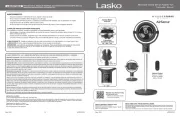
Lasko AK110LS6 Handleiding
Lasko
Ventilator
AK110LS6
Bekijk gratis de handleiding van Lasko AK110LS6 (12 pagina’s), behorend tot de categorie Ventilator. Deze gids werd als nuttig beoordeeld door 85 mensen en kreeg gemiddeld 4.6 sterren uit 43 reviews. Heb je een vraag over Lasko AK110LS6 of wil je andere gebruikers van dit product iets vragen? Stel een vraag
Pagina 1/12

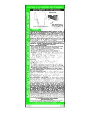
IMPORTANT INSTRUCTIONS -
OPERATING MANUAL
SAVE THESE INSTRUCTIONS
www.airkinglimited.com
6728081 Rev. D 1-16 1 of 12
Exhaust Fan
AKLS, AKLS6, AKLS6H Series
READ AND SAVE THESE INSTRUCTIONS
READ CAREFULLY BEFORE ATTEMPTING TO ASSEMBLE, INSTALL, OPERATE OR MAINTAIN
THE PRODUCT DESCRIBED. PROTECT YOURSELF AND OTHERS BY OBSERVING ALL SAFETY
INFORMATION. FAILURE TO COMPLY WITH INSTRUCTIONS COULD RESULT IN PERSONAL
INJURY AND/OR PROPERTY DAMAGE!
RETAIN INSTRUCTIONS FOR FUTURE REFERENCE.
GENERAL SAFETY INFORMATION
When using electrical appliances, basic precautions should
always be followed to reduce the risk of fire, electric shock and
injury to person, including the following:
WARNING: TO REDUCE THE RISK
OF FIRE, ELECTRIC SHOCK AND INJURY TO
PERSON, OBSERVE THE FOLLOWING:
a) Use this unit only in the manner intended by the manufacturer. If you have
questions, contact the manufacturer.
b) Before servicing or cleaning the unit, switch power off at service
panel and lock the service disconnecting means to prevent power
from being switched on accidentally. When the service disconnecting
means cannot be locked, securely fasten a prominent warning
device, such as a tag, to the service panel.
WARNING: TO REDUCE THE RISK
OF FIRE, ELECTRIC SHOCK AND INJURY TO
PERSON, OBSERVE THE FOLLOWING:
a) Installation work and electrical wiring must be done by qualified
person(s) in accordance with all applicable codes and standards,
including fire-related construction.
b) Sufficient air is needed for proper combustion and exhausting of
gases through the flue (chimney) of fuel burning equipment to prevent
back drafting. Follow the heating equipment manufacturer’s guideline
and safety standards such as those published by the National Fire
Protection Association (NFPA) and the American Society for Heating,
Refrigeration, and Air Conditioning Engineers (ASHRAE), and the local
code authorities.
c) When cutting or drilling into wall or ceiling, do not damage electrical
wiring and other hidden utilities.
CAUTION: FOR GENERAL VENTILATING USE ONLY.
DO NOT USE TO EXHAUST HAZARDOUS OR EXPLOSIVE
MATERIALS AND VAPORS.
d) Ducted fans must always be vented to the outdoors.
e) This unit must be grounded.
f) To avoid motor bearing damage and noisy and/or unbalanced impellers,
keep drywall spray, construction dust, etc. off power unit.
g) Read all instructions before installing or using exhaust fan.
WARNING: TO REDUCE THE RISK OF FIRE,
ELECTRIC SHOCK, DO NOT USE THIS FAN WITH
ANY SOLID-STATE SPEED CONTROL DEVICE.
a) If this unit is to be installed over a tub or shower, it must be
marked as appropriate for the application and be connected to a
GFCI (Ground Fault Circuit Interrupter) – protected branch circuit.
WARNING: DO NOT USE IN KITCHENS.
WARNING: THE DUCTING FROM THIS FAN TO THE
OUTSIDE OF THE BUILDING HAS A STRONG EFFECT
ON THE AIR FLOW, NOISE AND ENERGY USE OF THE FAN. USE
THE SHORTEST, STRAIGHTEST DUCT ROUTING POSSIBLE FOR
BEST PERFORMANCE, AND AVOID INSTALLING THE FAN WITH
SMALLER DUCTS THAN RECOMMENDED. INSULATION AROUND
THE DUCTS CAN REDUCE ENERGY LOSS AND INHIBIT MOLD
GROWTH. FANS INSTALLED WITH EXISTING DUCTS MAY NOT
ACHIEVE THEIR RATED AIRFLOW.

INSTALLATION INSTRUCTIONS
CAUTION: MAKE SURE POWER IS SWITCHED OFF AT
SERVICE PANEL BEFORE STARTING INSTALLATION.
SECTION 1
Preparing the Exhaust Fan
1. Unpack fan from the carton and confirm that all pieces are present. In addition to the
exhaust fan you should have:
1 - Grill
1 - Damper Assembly (attached)
4 - Mounting Rails
1 - Instruction/Safety Sheet
2. Choose the location for your fan. To ensure the best air and sound performance, it
is recommended that the length of ducting and the number of elbows be kept to a
minimum, the radius of each elbow be as large as possible for the installation, and that
insulated hard ducting be used. This fan will require
at least 8” of clearance in the ceiling or wall, and
will mount through drywall up to 3/4” thick. The fan
mounts between 16” or 24” on center joists using the
4 provided mounting rails.
3. Select the most convenient electrical knockout and
remove using a straight-blade screw driver (Figure 1).
4. No additional vibration deadening materials are
needed for this fan.
SECTION 2
New Construction
1. Install the rails into the mounting channel on the housing. Center the mounting channel in
the slots on the housing, then from inside the housing tighten the mounting channel screws
so the channel is securely in place. Position the housing next to the joist. Line up housing so
that it will be flush with the finished ceiling. Secure the ends of the rails with screws or nails
(not included) to the joists and slide the housing into the final position (Figure 2).
SECTION 3
Existing Construction
1. Set housing in position between the joist and trace an outline onto the ceiling material
(Figure 3). Set housing aside and cut opening, being careful not to cut or damage any
electrical or other hidden utilities. Install the rails into the mounting channel on the
housing. Center the mounting channel in the slots on the housing, then from inside
the housing tighten the mounting channel screws so the channel is securely in place.
Position the housing in the previously cut hole so that it is flush with the finished ceiling.
Secure the ends of the rails to the joists (Figure 2).
www.airkinglimited.com
6728081 Rev. D 1-16 2 of 12
SECTION 4
Ducting
NOTE: 4" (LS) OR 6" (LS6, LS6H) OR LARGER RIGID DUCT IS RECOMMENDED FOR BEST
PERFORMANCE.
CAUTION: ALL DUCTING MUST COMPLY WITH LOCAL AND
NATIONAL BUILDING CODES.
NOTE: The ducting from this fan to the outside of the building has a strong effect on the air
flow, noise and energy use of the fan. Use the shortest, straightest duct routing possible
for best performance, and avoid installing the fan with smaller ducts than recommended.
Insulation around the ducts can reduce energy loss and inhibit mold growth. Fans installed
with existing ducts may not achieve their rated air flow.
1. Connect the proper size ducting (AKLS - 4" round, AKLS6, AKLS6H, 6" round) to the
fan’s duct collar Secure in place using tape or screw clamp. Always duct (Figure 4).
the fan to the outside through a wall or roof cap. It is recommended that low restriction
termination fittings be used.
2. Ensure duct joints and exterior penetrations are sealed with caulk or other similar
material to create an air-tight path to minimize building heat loss or gain and to reduce
the potential for condensation. Place/wrap insulation around duct and/or fan in order to
minimize possible condensation buildup within the duct, as well as building heat loss or
gain (Figure 5).
SECTION 5
Wiring
CAUTION: MAKE SURE POWER IS SWITCHED OFF AT
SERVICE PANEL BEFORE STARTING INSTALLATION.
CAUTION: ALL ELECTRICAL CONNECTIONS MUST BE
MADE IN ACCORDANCE WITH LOCAL CODES, ORDINANCES, OR
NATIONAL ELECTRICAL CODE. IF YOU ARE UNFAMILIAR WITH METHODS OF INSTALLING
ELECTRICAL WIRING, SECURE THE SERVICES OF A QUALIFIED ELECTRICIAN.
NOTE: This unit includes a side access panel for wiring that does not require the removal of the
fan’s blower assembly. If you choose to wire the unit from the inside, you will need to remove
the blower assembly and internal wiring compartment. Both methods are equally effective.
1a. Remove the wire compartment cover screw and place External Wire Compartment:
cover in a secure place (Figure 6).
Figure 1
Figure 2
Housing
Joist
Mounting Rails
Ducting
Duct
Collar
Figure 4
Figure 3
Joist
Figure 5
Insulation*
(place around and
over Fan Housing
Fan Housing
Power Cable*
Seal gaps
around Housing
Round
Duct*
Seal duct joints
with tape
Round
Elbows*
Wall Cap*
Roof Cap*
(with built-in
damper)
Keep duct
runs short
*Purchase separately
or

1b. If the motor is already installed in the housing, remove Internal Wire Compartment:
the two screws holding the blower assembly in place. Lift up on the assembly and slide
it out of the tabs on the housing . Remove the wire compartment cover screw (Figure 7)
and place the cover in a secure place (Figure 8).
NOTE: If the fan motor plug is connected to the fan housing receptacle, unplug so the blower
assembly can be completely removed.
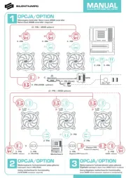
Standard Models
2a. Run wiring from an approved wall switch carrying the appropriate rating. One neutral
(white), one ground (green or bare copper), and one hot (black lead connected to the switch).
Secure the electrical wires to the housing with an approved electrical connector. Make sure
you leave enough wiring in the box to make the connection to the fan’s receptacle.
2b. From where you have chosen to access the fan’s junction box, connect the White wire
from the house to the White wire from the fan’s receptacle. Connect the Black wire from
the wall switch to the Black wire from the fan’s receptacle. Connect the ground wire
from the house to the Green wire from the fan’s receptacle . Use approved (Figure 9)
methods for all connections.
Humidity Sensing Models
3a. For proper operation the humidity sensing fan will require a 3 way switch (not included).
Run wiring between the fan and the switch location. Make sure you leave enough wiring
in each box to make the connections. At the switch box connect the Black wire from
the house to the common terminal of the switch. Connect the black wire from the fan to
www.airkinglimited.com
6728081 Rev. D 1-16 3 of 12
one of the switched terminals on the switch. This position will energize the automatic
mode and the fan will energize upon a rise in humidity. Connect the Red wire from the
fan to the other switched terminal on the switch. This position will activate the Manual
On feature and energize the fan. Properly connect the ground and neutral (if applicable)
mount the switch and the cover.
3b. From where you have chosen to access the fan’s junction box, connect the white wire
from the house to the white wire from the fan. Connect the wire from the automatic
position on the wall switch to the black wire from the fan, connect the wire from the
manual On position on the switch to the red wire from the fan. Connect the ground
wire from the house to the green wire from the fan housing . Use approved (Figure 10)
methods for all connections.
NOTE: The fan’s receptacle wires might need to be pulled outside compartment for connection.
Only pull the three loose wires outside of compartment. Additional wires will be present.
4. Carefully tuck wire back inside wire compartment and replace wire compartment cover
securing with the screw that was removed earlier.
SECTION 6
Completing the Installation
1. Use a sealant appropriate for contact with the building materials present and for the
temperature requirements of the installation to prevent air leakage from unconditioned
spaces is recommended. If gaps between unit housing and ceiling are great, additional
material (backing rod, ceiling material) may be required.
NOTE: This fan is rated for direct insulation contact (Type IC) and it is recommended that this fan
be completely covered by insulation in order to reduce heat loss or gain to unconditioned space.
2. If the fan’s blower assembly was removed during the wiring process, reinstall the
blower by reversing the directions in (Wiring), Section 5 Step 1b.
3a. Plug the fan’s quick connect motor cord into the receptacle. This cord AKLS MODELS:
will only fit one way into the receptacle (Figure 11).
3b. AKLS6 MODELS: Plug the fan’s 5 pin quick connect motor cord into the included
harness. Plug the 3 pin quick connect harness cord into the receptacle located on top of
the wire compartment. These cords will only fit one way into the receptacles (Figure 12).
Figure 6
Screw
Wire
Compartment
Cover
Figure 9
Supply from
house
Ground White
Hot (Black)
Figure 8
Screw
Wire Compartment
Cover
NOTE: Wire compartment configuration will be dependent on model.
Figure 11
Figure 10
Supply from house
Ground White
Hot (Black) Red
Figure 12
Plug
Figure 7
Screws
Tabs
Product specificaties
| Merk: | Lasko |
| Categorie: | Ventilator |
| Model: | AK110LS6 |
Heb je hulp nodig?
Als je hulp nodig hebt met Lasko AK110LS6 stel dan hieronder een vraag en andere gebruikers zullen je antwoorden
Handleiding Ventilator Lasko
14 Juni 2025
13 Juni 2025
17 Maart 2025

17 Maart 2025

17 Maart 2025
17 Maart 2025
17 Maart 2025

17 Maart 2025

17 Maart 2025

17 Maart 2025
Handleiding Ventilator
- SMC
- Fagor
- LC-Power
- Keystone
- Team
- Heylo
- Unold
- Concept
- Clatronic
- Casablanca
- JAP
- Mesko
- Magnavox
- Infiniton
- Qazqa
Nieuwste handleidingen voor Ventilator
30 Juli 2025
29 Juli 2025
29 Juli 2025
29 Juli 2025
28 Juli 2025
23 Juli 2025
23 Juli 2025
22 Juli 2025
22 Juli 2025
22 Juli 2025