Kimo PST Handleiding
Bekijk gratis de handleiding van Kimo PST (11 pagina’s), behorend tot de categorie Niet gecategoriseerd. Deze gids werd als nuttig beoordeeld door 4 mensen en kreeg gemiddeld 4.6 sterren uit 2.5 reviews. Heb je een vraag over Kimo PST of wil je andere gebruikers van dit product iets vragen? Stel een vraag
Pagina 1/11


English
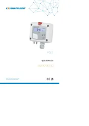
Quick Start Guide
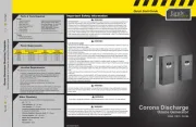
Manostats
Connections
Electrical connections as per NFC15-100 standard
NO COM NC
1 2 3 4 5 6 7
-
+
Alimentation
24 Vdc
ou
N L
N L
~ ~
~ ~
6 7
Alimentation
24 Vac
Classe II
NO COM NC
1 2 3 4 5 6 7
-
+
Power supply
24 Vdc
or
N L
N L
~ ~
~ ~
6 7
Power supply
24 Vac
Class II
NO COM NC
1 2 3 4 5 6 7
-
+
Alimentación
24 Vdc
o
N L
N L
~ ~
~ ~
6 7
Alimentación
24 Vac
Clase II
NO COM NC
1 2 3 4 5 6 7
-
+
Alimentazione
24 Vdc
o
N L
N L
~ ~
~ ~
6 7
Alimentazione
24 Vac
Classe II
This connection must be made by a qualied
and trained technician. To make the connection,
the transmitter must not be energized.
Settings and use of the transmitter
NO: normalement opened
COM: common
NC: normally closed
1. Solenoid valve (only PST-11)
2. Switchs
3. Switchs
4. Pressure connections
5. Autozero
6. LCC-S software connection
7. Alarm LED
8. Button for settings
9. Relay terminal block
10. Power supply terminal block
11. Cable gland
1
2
4
5
7
8
3
6
9
10
11
To perform an autozero, unplug the 2 pressure connections tubes and press the “Autozero” key.
On the PST-11 transmitter, it is not necessary to unplug the 2 pressure connection tubes.
When an autozero has been performed, “On” green light turns off then turns on, and “autoZ”
is displayed.
To congure the transmitter, unscrew the 4 screws from the housing then open it. DIP switches allowing the different
settings are then accessible.
To congure the transmitter, it must not be energized. Then, you can make the settings required, with the DIP switches
(as shown on the drawing below). When the transmitter is congured, you can power it up.
1
2
3
4
Switch actif
Interrupteur
Réglage
des unités
1
2
3
4
1
2
3
4
Switch actif (S1)
Active switch (S1)
1
2
3
4
Active switch
On-off switch
Units setting
1
2
3
4
Bloque derecho
Interruptor
Conguración
de unidades
1
2
3
4
Interruttore attivo
Interruttore
Impostazione
unità
• Units setting – right DIP switch
To set a unit of measurement, put the 1, 2 , 3 and 4 on-off switches as indicated in the table below.
• Conguration
Symbols used
For your safety and in order to avoid any damage of the device,
please follow the procedure described in this document and read
carefully the notes preceded by the following symbol:
The following symbol will also be used in this document, please
read carefully the information notes indicated after this symbol:
The PST is used to control pressure.
• Activate or deactivate an alarm
- Press the button for 3 seconds, “CONF” is displayed then “NEG”, meaning that the relay is in negative security, it is
excited during an alarm condition.
If needed, press quickly on the button to switch the relay in positive security, the relay is de-energized during an alarm
condition or a current breaking, “POS” is displayed.
- Press 3 s the button, “Buzz” screen is displayed with “ON” or “OFF” blinking. Briey press on the button to activate
(“ON”) or deactivate (“OFF”) (according to the last saved conguration) the buzzer during an alarm condition.
- Press 3 s the button, “Alarm” screen is displayed with “On” or “Off” blinking (according to the last saved
conguration).
- Press quickly the button, the display changes from “On” (activated alarm) to “Off” (deactivated alarm).
- Press 3 seconds the button to conrm the setting. If the alarm is deactivated, the instrument displays the
measurement; if the alarm is activated, the instrument displays the following setting.
• Threshold conguration
The button allows to activate or not an alarm (threshold), to set the action of the alarm (edge), to set the
threshold(s) value, to set the time-delay and to acknowledge the alarm.
Working principle:
- By pressing on the button more than 3 seconds, you can validate the setting and go to the next setting.
- By pressing quickly on the button, you can increment a value and scroll down the different option or values.
• Set the threshold(s) value
The rst digit blinks, it corresponds to the positive (0) or negative (-) setting of the threshold value. Press briey on the button
to select the sign for the threshold value. Press on the button more than 3 seconds to validate.
The second digit blinks, press briey on the button to scroll the numbers. Press the button more than 3 seconds to validate.
Repeat the process until the last digit to congure the threshold value, validate the threshold and go to the following setting.
If the monitoring edge has been selected, the transmitter displays the setting of the second threshold.
• Set the action of the alarm (rising edge or falling edge)
The edge determines the action of the alarm according to the trespassing direction of the threshold(s).
Rising edge(1 threshold): the alarm goes off when the measurement exceeds the threshold
and stops when it is below the threshold.
Falling edge(1 threshold): the alarm goes off when the measurement is below the threshold
and stops when it exceeds the threshold.
Monitoring (2 thresholds): the alarm goes off when the measurement is outside the dened
low and high thresholds.
Mode
Mode
Mode
Rising edge Falling edge Monitoring
Measurement (m) > Threshold (S) during the time-
delay T1: Alarm activation.
Measurement (m) < Threshold (S) - Hysteresis (H)
during the time-delay T2: Alarm deactivation.
Measurement (m) < Threshold (S) during the time-
delayT1: Alarm activation.
Measurement (m) > Threshold (S) + Hysteresis (H)
during time-delay T2: Alarm deactivation.
The alarm goes off when the measurement is
outside the low and high thresholds.
- Press briey the button to select the trespassing direction then press the button more than 3 seconds to validate this
direction and set the thresholds.
PST-14, PST-15
Congurations mbar inWG kPa PSI mmHG mmH
2
O daPa hPa
Combinations
1
2
3
4
1
2
3
4
1
2
3
4
1
2
3
4
1
2
3
4
1
2
3
4
1
2
3
4
1
2
3
4
1
2
3
4
1
2
3
4
1
2
3
4
1
2
3
4
1
2
3
4
1
2
3
4
1
2
3
4
1
2
3
4
1
2
3
4
1
2
3
4
1
2
3
4
1
2
3
4
1
2
3
4
1
2
3
4
1
2
3
4
1
2
3
4
1
2
3
4
1
2
3
4
1
2
3
4
1
2
3
4
1
2
3
4
1
2
3
4
1
2
3
4
1
2
3
4
1
2
3
4
1
2
3
4
1
2
3
4
1
2
3
4
1
2
3
4
1
2
3
4
1
2
3
4
1
2
3
4
1
2
3
4
1
2
3
4
1
2
3
4
1
2
3
4
1
2
3
4
1
2
3
4
1
2
3
4
1
2
3
4
1
2
3
4
1
2
3
4
1
2
3
4
1
2
3
4
1
2
3
4
1
2
3
4
1
2
3
4
1
2
3
4
1
2
3
4
1
2
3
4
1
2
3
4
1
2
3
4
1
2
3
4
1
2
3
4
1
2
3
4
1
2
3
4
PST-11, PST-12, PST-13
Congurations Pa mmH
2
O mbar inWG mmHG daPa kPa hPa
Combinations
1
2
3
4
1
2
3
4
1
2
3
4
1
2
3
4
1
2
3
4
1
2
3
4
1
2
3
4
1
2
3
4
1
2
3
4
1
2
3
4
1
2
3
4
1
2
3
4
1
2
3
4
1
2
3
4
1
2
3
4
1
2
3
4
1
2
3
4
1
2
3
4
1
2
3
4
1
2
3
4
1
2
3
4
1
2
3
4
1
2
3
4
1
2
3
4
1
2
3
4
1
2
3
4
1
2
3
4
1
2
3
4
1
2
3
4
1
2
3
4
1
2
3
4
1
2
3
4
1
2
3
4
1
2
3
4
1
2
3
4
1
2
3
4
1
2
3
4
1
2
3
4
1
2
3
4
1
2
3
4
1
2
3
4
1
2
3
4
1
2
3
4
1
2
3
4
1
2
3
4
1
2
3
4
1
2
3
4
1
2
3
4
1
2
3
4
1
2
3
4
1
2
3
4
1
2
3
4
1
2
3
4
1
2
3
4
1
2
3
4
1
2
3
4
1
2
3
4
1
2
3
4
1
2
3
4
1
2
3
4
1
2
3
4
1
2
3
4
1
2
3
4
1
2
3
4
Tolerated overpressure PST-11, PST-12: 21,000 Pa; PST-13: 69,000 Pa; PST-14: 1400 mbar; PST-15: 4100 mbar
Conditions of use (°C/%RH/m) From 0 to +50 °C. In non-condensing condition. From 0 to 2000 m.
Storage temperature From -10 to +70 °C
Protection IP65
Power supply 24 Vac/Vdc ±10%
Consumption 3 VA
Inside the front housing
Removable front face
Fixed back housing
Product specificaties
| Merk: | Kimo |
| Categorie: | Niet gecategoriseerd |
| Model: | PST |
Heb je hulp nodig?
Als je hulp nodig hebt met Kimo PST stel dan hieronder een vraag en andere gebruikers zullen je antwoorden
Handleiding Niet gecategoriseerd Kimo
16 September 2025
15 September 2025

15 September 2025

15 September 2025
15 September 2025
3 September 2025

1 September 2025

1 September 2025
1 September 2025
1 September 2025
Handleiding Niet gecategoriseerd
- Anchor Audio
- Chamberlain
- Sweet Alice
- MSR
- Traxxas
- Moleskine
- Cinderella
- Cool Head
- Marker
- Ices
- FANAUE
- Zanussi
- AC Infinity
- Rupert Neve Designs
- Megger
Nieuwste handleidingen voor Niet gecategoriseerd
16 September 2025

16 September 2025
16 September 2025

16 September 2025

16 September 2025

16 September 2025

16 September 2025
16 September 2025

16 September 2025

16 September 2025