Heatit ZM Handleiding


Lees hieronder de 📖 handleiding in het Nederlandse voor Heatit ZM (6 pagina's) in de categorie Niet gecategoriseerd. Deze handleiding was nuttig voor 115 personen en werd door 2 gebruikers gemiddeld met 4.5 sterren beoordeeld

Pagina 1/6
1. INTRODUCTION
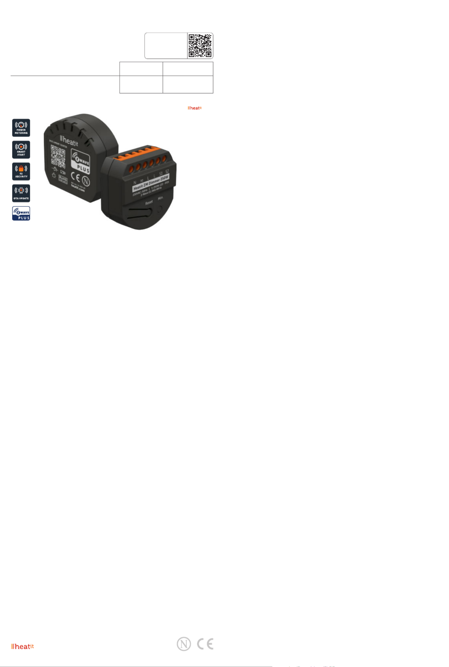
Heatit ZM Dimmer is an inwall dimmer for installation in
European electrical wall boxes. The dimmer enables the user
to control light sources from the Z-Wave network and/or an
external switch.
The Heatit ZM Dimmer works on most low loads of both
LEDs and other light fixtures without causing flickering. When
connecting low loads it is recommended to use a bypass.
The dimmer may be connected to two external switches
that can be used to control the lights, associated devices and
scenes.
Heatit ZM Dimmer has active power metering and it gives you
real time information about your power consumption.
NB! DIMMING
Dimming may be challenging, and we recommend checking
the compatibility of dierent light sources before installation.
We are happy to answer any questions.
2. STATEMENT REGARDING PRODUCTS FROM MULTIPLE
MANUFACTURERS
Please read this before installation
This device may be used with all devices certified with the
Z-Wave Plus™ certificate and should be compatible with
such devices produced by any manufacturer. Every primary
controller is dierent depending on the manufacturer, their
target audience and intended use/application. Please review
the functionalities implemented by the primary controller you
intend to use with our Z-Wave Plus certified device to ensure
that it provides the necessary controls to take full advantage of
our product’s capabilities.
3. BEHAVIOUR WITHIN THE Z-WAVE NETWORK
This device may be operated within any Z-Wave™ network
with Z-Wave-certified devices from other manufacturers. All
non-battery-operated nodes within the network will act as
repeaters regardless of manufacturer to increase the reliability
of the network. On delivery, the device does not belong to any
Z-Wave network. The device needs to be added to an existing
network to communicate with the other devices within it.
Devices may also be removed from a network. The add/
remove processes are initiated by the primary controller of the
Z-Wave network.
TABLE OF CONTENTS
1. Introduction
2. Statement regarding products from multiple
manufacturers
3. Behaviour within the Z-Wave network
4. Quick start
5. Illustrations
6. Installation guidelines
7. External switch
8. Add/remove
8.1 Standard (Manual)
8.2 SmartStart (Automatic)
9. Factory reset
10. Startup
11. LED blinking patterns description
12. QR-code placement (DSK)
13. Security
14. Node Information Frame
15. Associations
15.1 Setting and removing associations
16. Association groups
17. Configuration parameters
18. Autocalibration of maximum dim level
19. Manual calibration of minimum dim level
20. ON/OFF functionality
21. Overload protection
22. Command Classes
22.1 Basic Command Class
22.2 Multilevel Switch Command Class
22.3 Meter Command Class
22.4 Indicator Command Class
22.5 Central Scene Command Class
22.6 Notification Command Class
23. Supported Command Classes
Product info
HEATIT ZM
DIMMER
Installers manual
Firmware version Document version
FW 1.0 2023-B
Article no. Document date
14 444 49 01.06.2023
Org. doc. date 01.02.2023
TO PRODUCT
DOCUMENTS
4. QUICK START
1. Switch o the mains voltage (turn o the fuse).
2. Open the junction box.
3. Connect according to the wiring diagram as shown in
chapter 6 “Installation & wiring”.
4. After verifying the connections, switch on the mains voltage.
5. Set the primary controller in add mode
(security/non-security).
6. Press the reset button on dimmer 3 times in a rapid
sequence. The Heatit ZM Dimmer is now included in your
Z-Wave network.
5. ILLUSTRATIONS
6. INSTALLATION GUIDELINES
Installation must be done by a qualified electrician in
accordance with national building codes. Before installation,
disconnect the power to the device from the mains. During
installation of the device, power to the device must be
disconnected AT ALL TIMES!
Max tightening torque for terminal screws: 2Nm
NB! The dimmer can be used in a 2 and 3-wire mode. In
2-wire mode, neutral can only be connected to the load and
not the dimmer itself. The dimmer automatically detects if it is
connected in 2 or 3-wire mode.
1. Turn o the fuse.
2. Connect the Live to the dimmer terminal marked ”L.
Optional: Connect the Neutral to the dimmer terminal
marked ”N”.
3. Connect the load terminal marked ”L to the dimmer terminal
marked
4. Connect the load terminal marked “N” directly to Neutral.
5. Install the dimmer in the junction box.
Make sure that no wires are pinched.
21mm
45mm
46mm
S1: External momentary switch. Used for dimming the load
Can be used as a scene controller.
S2: External momentary switch. Can be used for either
dimming or scene controller.
Wiring diagram
7. EXTERNAL SWITCH
Momentary Switch (NO)
When using external switches, the switch functionality can be
selected using Parameter 6 and 7. The connected switches
must be normally open switches.
8. ADD/REMOVE
The primary controller/gateway has a mode for adding or
removing devices. Please refer to your primary controller
manual on how to set the primary controller in add/remove
mode.
The device may only be added or removed from the network
if the primary controller is in add/remove mode. When the
device is removed from the network, it will NOT revert to
factory settings.
An always listening node must be powered continuously
and reside in a fixed position in the installation to secure the
routing table. Adding the device within a 2 meters range from
the gateway can minimize faults during the Interview process.
There are two ways to add the device to a Z-Wave network.
8.1 Standard (Manual)
Add/remove mode is indicated on the device by a blinking
green LED. It indicates this for 90 seconds until a timeout
occurs, or until the module has been added to/removed
from the network. Configuration mode can also be cancelled
by performing the same procedure used for starting
Configuration mode.
To start the configuration process, press the reset button 3
times in rapid succession. The LED will light up in solid green
for 3 seconds if add/remove is successful. The device is now
ready for use with default settings.
Switch 2
Switch 1
Last/Load
L N
2-wire
Switch 2
Switch 1
Last/Load
L N
3-wire
Reset button
Figure 2 (fail)
If the button is released before the 3
seconds period, the device will indicate
fail by turning RED LED on for 3 seconds.
Figure 3 (fail)
The button MUST be released between
20 and 23 seconds for local reset to take
place. If held longer, the device will ignore
the command.
12. QR-CODE PLACEMENT (DSK)
The QR-code is needed when including a device using S2
security or SmartStart. The DSK can be found in the QR-code
and is located;
On the product.
In the Quick Guide.
On the packaging box/gift box.
13. SECURITY
S2 security enhances Z-Wave Plus with an additional layer of
AES 128-bit encryption of the wireless Z-Wave communication
to prevent hacking and man-in-middle attacks on the home
network. This device supports S2 and has a Z-Wave DSK QR-
code label that may be used when the module is added to the
Z-Wave home network. The primary controller will ask for a
5-digit code, which can be found underneath the QR-code.
14. NODE INFORMATION FRAME
The node information frame is the ”business card” of a Z-Wave
device. It contains information about the device type and its
technical features.
The add and remove procedure of the device is confirmed by
sending out a node information frame. Besides this, it may be
necessary for certain network operations to send out a node
information frame.
15. ASSOCIATIONS
Z-Wave devices interact with other Z-Wave devices. The
relationship between one device controlling another device is
called an association. In order to control a subordinate device,
the controlling device needs to maintain a list of devices that
will receive controlling commands. These lists are called
”Association groups”. They are always related to the specific
event triggered (e.g., sensor reports). In case the event is
triggered, all devices stored in the respective association group
will receive a joint wireless command.
15.1 Setting and Removing Associations
Associations may be assigned and removed via Z-Wave
commands. Please refer to your primary controller/Z-Wave
gateway for more information.
0s 1s
0,5s 2s 3s 4s 5s
3<x<20s
Released @ x seconds
6<x+3<23s
0s 1s
0,5s
2s 3s 4s 5s 19s 20s 21s 22s 23s 24s20,5s 21,5s 22,5s
NB! When the device is removed from the gateway, the
parameters are not reset. To reset the parameters, see ”Factory
reset”.
If inclusion fails, please perform a ”remove device” process and
try again. If inclusion fails again, please see “Factory reset”.
8.2 SmartStart (Automatic)
SmartStart enabled products may be added to a Z-Wave
network by scanning the Z-Wave QR-code on the product
if your primary controller supports SmartStart inclusion. No
further action is required and the SmartStart product will be
added automatically after being powered on within range of
the primary controller.
9. FACTORY RESET
Please read this before installation
Press and hold the reset button. After 3 seconds the LED will
start to blink green. After 20 seconds the LED will start blinking
green rapidly. You may now release the button. If reset was
successful the LED will light up in solid green for 3 seconds.
Please use this procedure only when the network primary
controller is missing or otherwise inoperable.
10. STARTUP
After powering up the device for the rst time, all the parameters will
have default settings.
11. LED BLINKING PATTERNS DESCRIPTION
The device supports numerous LED blinking patterns to make
it as easy as possible to identify what the device is doing.
Device Not in Network
The LED will blink red when the device is
not added to a Z-Wave network.
0s 1s
0,5s 2s 3s 4s 5s
Add/Remove
When device enters add/remove mode
the LED will blink green.
If successful, the LED will light up in solid
green for 3 seconds.
If unsuccessful, the LED will light up in
solid red for 3 seconds.
0s 1s
0,5s 2s 3s xs x+3s
Successful
Unsuccessful
Factory Reset
If the button is held for more than 3 seconds, the GREEN LED will start blinking with 0.5s intervals.
When the button has been held for 20 seconds, the GREEN LED will blink rapidly with 0.1s intervals for 3 seconds.
Figure 1 (success)
Within the 3 second period the button must be released.
If the button is released within this period, the device will indicate that it has been successfully reset by lighting up in
solid GREEN for 3 seconds. The device will then start blinking RED because it is not included in a gateway.
0s 1s
0,5s 2s 3s 4s 5s 19s 20s 0,5s 1,5s 2,5s
1s 2s 3s 1s 2s 3s


Product specificaties

Merk: Heatit
Categorie: Niet gecategoriseerd
Model: ZM

Heb je hulp nodig?

Als je hulp nodig hebt met Heatit ZM stel dan hieronder een vraag en andere gebruikers zullen je antwoorden


Handleiding Niet gecategoriseerd Heatit

Handleiding Niet gecategoriseerd

Nieuwste handleidingen voor Niet gecategoriseerd