EXSYS EX-62026POE Handleiding
EXSYS Netwerkkaart/adapter EX-62026POE
Bekijk gratis de handleiding van EXSYS EX-62026POE (2 pagina’s), behorend tot de categorie Netwerkkaart/adapter. Deze gids werd als nuttig beoordeeld door 32 mensen en kreeg gemiddeld 4.9 sterren uit 8 reviews. Heb je een vraag over EXSYS EX-62026POE of wil je andere gebruikers van dit product iets vragen? Stel een vraag
Pagina 1/2
PoE Budget
Total max.
Port 1-830W / Port240W@48V120W@24V70W@12V
Port 9+10- - - -
6
5
1
AnleitungAnleitung
Vers. 1.0 / 20.07.25
ATTENTION!
Please pay attention to the correct polarity!
Never connect the power supply to the terminal block
while it is switched on!
Redundant power supply possible to reduce operational failure.
Both power supplies must use the same voltage!
EX-62026PoE
Kompatibilität:Gigabit Ethernet 10/100/1000Base-T
PoE:IEEE 802.3af/at (PoE+), Mode/Alternative B
Betriebssysteme:Alle Betriebssysteme
Anschlüsse:10x RJ45-Buchse (8x PoE+), 1x Terminal Block 12~48VDC
Lieferumfang:EX-62026PoE, DIN-Rail Kit, Wandmontagebügel, Anleitung
Der extrem kompakte industrietaugliche 10-Port Gigabit PoE-Switch EX-62026PoE bietet trotz
seiner äusserst geringen Aussenmaße volle Gigabit Leistung an allen 10 Ports. An acht
Downlink-Ports stehen jeweils bis zu 30W für den Anschluss von PoE Power Devices (PD) wie
z.B. IP-Kameras oder IP-Telefone zur Verfügung. Dank dem robusten Metallgehäuse und dem
erweiterten Betriebstemperaturbereich von -40°C bis 80°C ist er für eine Vielzahl von
Anwendungen auch in rauen Umgebungen geeignet. Die Stromversorgung erfolgt über den
Terminal Block (12-48 VDC) und kann zur Verminderungen von Betriebsausfällen auch
redundant erfolgen. Der EX-62026PoE unterstützt Auto-MDI/MDI-X und Auto-Negotation.
BESCHREIBUNG & TECHNISCHE DATEN
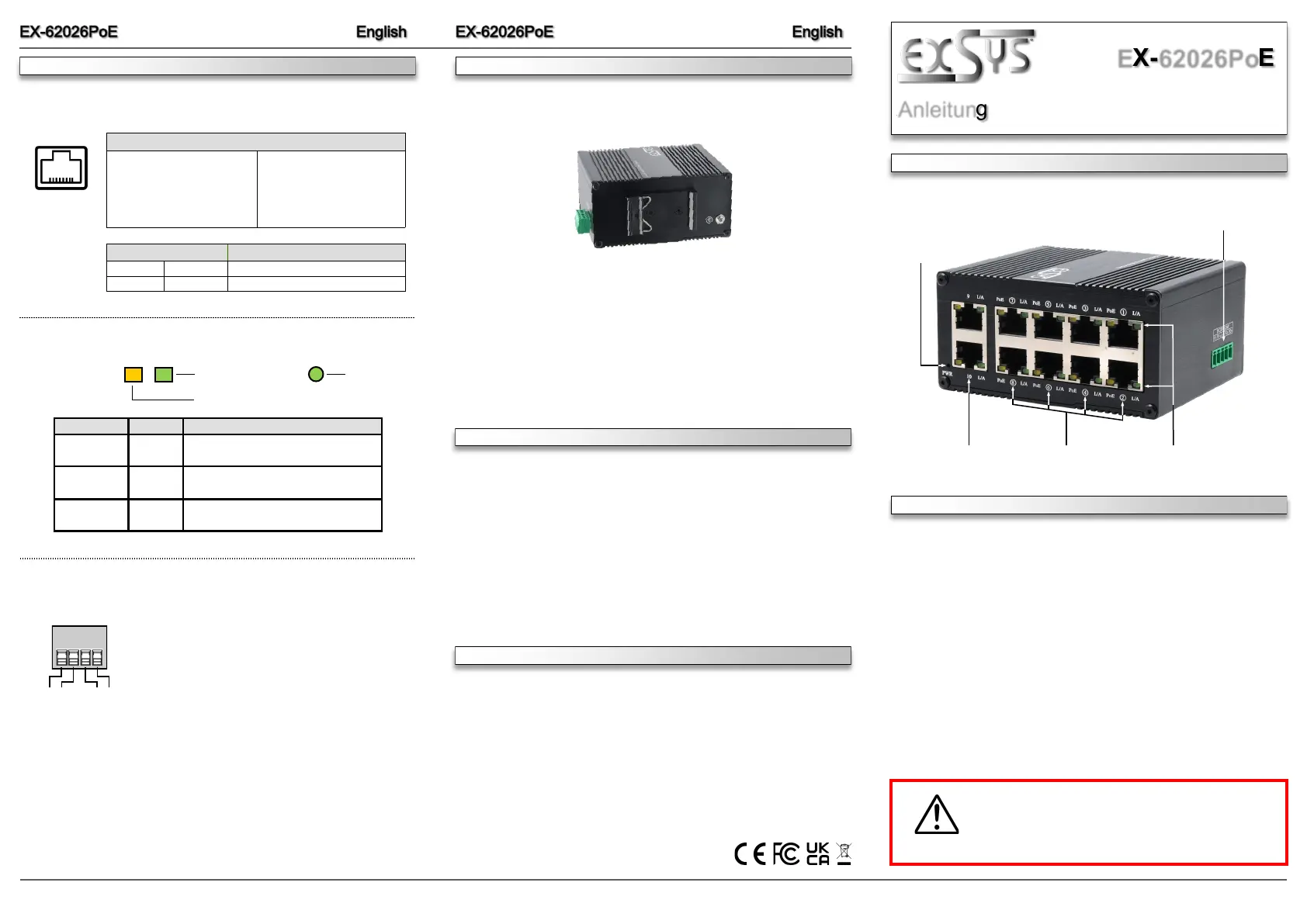
AUFBAU
12-48V T-Block für optional
erhältliches Netzteil
Betriebs LED
8x RJ45
Gigabit PoE
PoE / Status-LEDs2x RJ45
100/1000 Mbit/s
Please read the following installation instructions.
1.Install the EX-62026POE on a mounting rail using the DIN-Rail kit.
2.Connect the power connector of the optionally available power supply to the terminal block
and turn on the power supply.
3.When the power is turned on, the PWR indicator lights up. If the indicator is not lit, check
for proper connection to the power supply.
4.Connect your network devices to the switch using a network cable.
5.If all cables are connected correctly, the indicators light according to the port status of the
LEDs (page 5).
HARDWAREINSTALLATION
CONNECTORS & LEDs
87654321
RJ45 Port
PinSignalPoEPinSignalPoE
1BI_DA+ 5BI_DC- VCC+
2BI_DA- 6BI_DB-
3BI_DB+ 7BI_DD+VCC-
4BI_DC+VCC+8BI_DD- VCC-
PoE LED
LINK / Activity LED
12V to 48V T-Block:
Status LEDs:
LED NameColorLED Function
L/AGreen
On:Linked
Flashing:Data Transmission
PoEYellow
On:PoE is activated
Flashing:Power Device (PD) detected
Off:No (PD) device connected
Power
Green
On:Powered
Off:Power off
V- V+
V- V+
RJ45 Port:
PWR LED
Power over Ethernet IEEE802.3af/at (PoE+), Mode B
ACHTUNG!
Bei geerdetem Minuspol der Stromversorgung
unbedingt den Technischen Hinweis auf Seite 3
beachten.
To clean the unit, use only a dry, lint-free cloth and apply light pressure to remove dirt. Take
care not to leave any fibres of the cloth in the connectors.
Never use a damp or wet cloth for cleaning!
CLEANING
TECHNICAL NOTE
Procedure for STP Cable Grounding
When using shielded cables to connect two Ethernet devices, a ground loop may occur if the
shielding on the cables generates an additional grounding connection path. This can cause
ground current to flow through to the Ethernet ports and damage the devices. If it is necessary
to use shielded cables, we recommend using a metallic RJ45 connector on one end and a non-
metallic connector on the other end. Alternatively, a patch panel can be used in between the
two devices to prevent ground loops from occurring.
For connections over short distances (e.g., between two devices installed in the same cabinet),
both ends of the shielded cable can be referenced to the same grounding point. Therefore, in
this case, it is acceptable to use a shielded cable with metallic RJ45 connectors on both
devices.
The DIN-Rail Kit is pre-assembled
on the rear side
Switzerland:
EXSYS Vertriebs GmbH
Dübendorfstrasse 17
8602 Wangen
www.exsys.ch
Germany:
EXSYS Vertriebs GmbH
Industriestrasse 8
61449 Steinbach
www.exsys.de
Italy:
EXSYS Italia Srl
Via Belvedere, 45/B
I-22100 Como
www.exsys.it
Product specificaties
| Merk: | EXSYS |
| Categorie: | Netwerkkaart/adapter |
| Model: | EX-62026POE |
Heb je hulp nodig?
Als je hulp nodig hebt met EXSYS EX-62026POE stel dan hieronder een vraag en andere gebruikers zullen je antwoorden
Handleiding Netwerkkaart/adapter EXSYS

6 Mei 2026
4 Mei 2026
3 Maart 2026
3 Maart 2026
3 Maart 2026
3 Maart 2026
2 Maart 2026
2 Maart 2026
2 Maart 2026
1 December 2025
Handleiding Netwerkkaart/adapter
Nieuwste handleidingen voor Netwerkkaart/adapter
18 Mei 2026
12 Mei 2026
2 April 2026
31 Maart 2026
28 Maart 2026
27 Maart 2026
27 Maart 2026
27 Maart 2026
26 Maart 2026
26 Maart 2026