Ernitec 0070-08215 Handleiding
Ernitec Bewakingscamera 0070-08215
Bekijk gratis de handleiding van Ernitec 0070-08215 (2 pagina’s), behorend tot de categorie Bewakingscamera. Deze gids werd als nuttig beoordeeld door 25 mensen en kreeg gemiddeld 4.3 sterren uit 7 reviews. Heb je een vraag over Ernitec 0070-08215 of wil je andere gebruikers van dit product iets vragen? Stel een vraag
Pagina 1/2
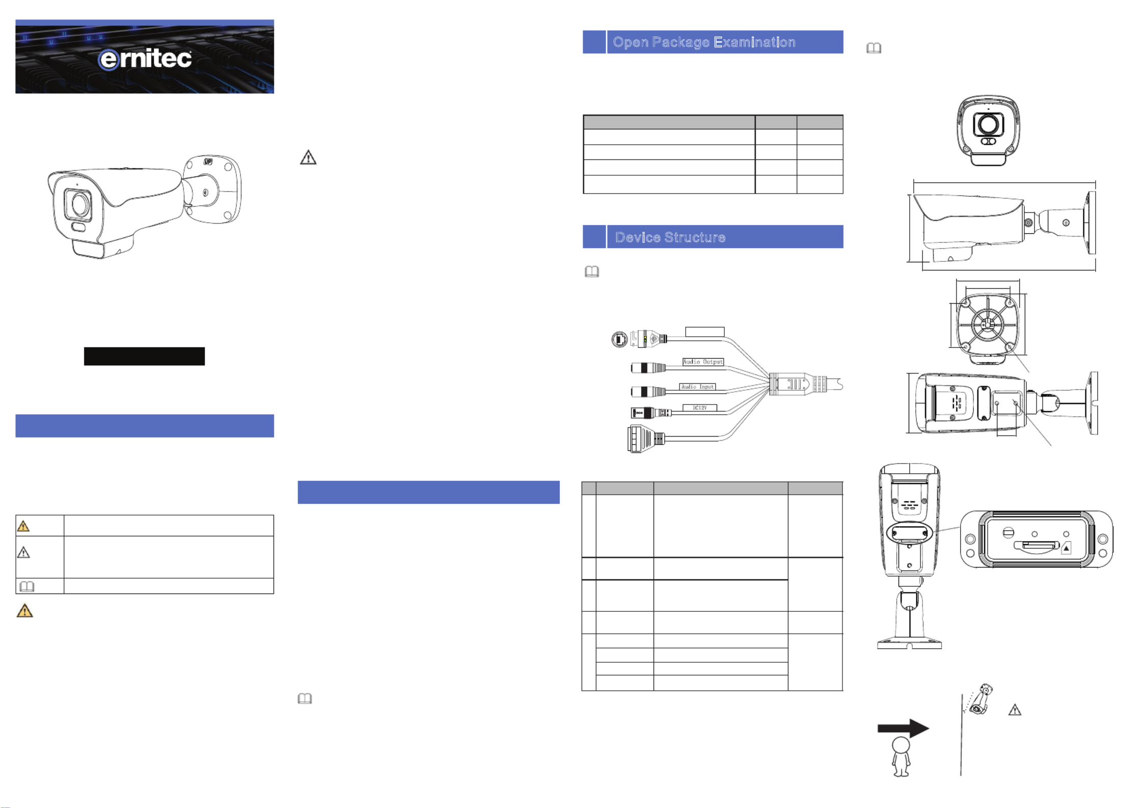
22Camera Dimensions.
Figure 22 -Dimensions (Unit: mm)
Special Announcement
, For more informationplease refer to website.
Fully understand this document before using this device,
and strictly observe rules in this document when using this
device. If you install this device in public places, provide the
tip "You have entered the area of electronic surveillance" in
an eye-catching place. Failure to correctly use electrical
products may cause fire and severe injuries.
ŸStrictly observe installation requirements when installing
the device. The manufacturer shall not be held responsible
for device damage caused by users' non-conformance to
these requirements.
ŸStrictly conform to local electrical safety standards and use
power adapters that are marked with the LPS standard
when installing and using this device. Otherwise, this
device may be damaged.
ŸUse accessories delivered with this device. The voltage
must meet input voltage requirements for this device.
ŸIf this device is installed in places with unsteady voltage,
ground this device to discharge high energy such as
electrical surges in order to prevent the power supply from
burning out.
ŸWhen this device is in use, ensure that no water or any
ŸAvoid heavy loads, intensive shakes, and soaking to
prevent damages during transportation and storage. The
warranty does not cover any device damage that is caused
during secondary packaging and transportation after the
original packaging is taken apart.
ŸProtect this device from fall-down and intensive strikes,
keep the device away from magnetic field interference, and
do not install the device in places with shaking surfaces or
under shocks.
ŸClean the device with a soft dry cloth. For stubborn dirt, dip
the cloth into slight neutral cleanser, gently wipe the dirt
with the cloth, and then dry the device.
ŸDo not jam the ventilation opening. Follow the installation
instructions provided in this document when installing the
device.
ŸKeep the device away from heat sources such as radiators,
electric heaters, or other heat equipment.
ŸKeep the device away from moist, dusty, extremely hot or
cold places, or places with strong electric radiation.
ŸIf the device is installed outdoors, take insect- and
moisture-proof measures to avoid circuit board corrosion
that can affect monitoring.
ŸRemove the power plug if the device is idle for a long time.
ŸBefore unpacking, check whether the fragile sticker is
damaged. If the fragile sticker is damaged, contact
customer services or sales personnel. The manufacturer
shall not be held responsible for any artificial damage of the
fragile sticker.
ŸAll complete products sold by the manufacturer are
delivered along with nameplates, quick setup guide and
accessories after strict inspection. The manufacturer shall
not be held responsible for counterfeit products.
ŸThe manufacturer will update this manual according to
product function enhancement or changes and regularly
update the software and hardware described in this manual.
Update information will be added to new versions of this
manual without prior notice.
ŸThis manual may contain misprints, technology information
that is not accurate enough, or product function and
operation description that is slightly inconsistent with the
actual product, the final interpretation of company is as a
standard.
ŸThis manual is only for reference and does not ensure that
the information is totally consistent with the actual product.
For consistency, see the actual product.
Precautions
Open the package, check the appearance of product for no
obvious damage, and confirm the item list for table 1-1 is
consistent.
Table 1 1-Packing list
2.1 Device Ports
Different devices may have different ports, multi-head cables,
and fill lights; Please refer to the actual product.
Different devices may have different dimensions; Please
refer to the actual product.
NOTE
NOTE
NOTE
liquid flows into the device. If water or liquid unexpectedly
flows into the device, immediately power off the device and
disconnect all cables (such as power cables and network
cables) from this device.
ŸDo not focus strong light (such as lighted bulbs or sunlight)
on this device. Otherwise, the service life of the image
sensor may be shortened.
ŸIf this device is installed in places where thunder and
lightning frequently occur, ground the device nearby to
discharge high energy such as thunder strikes in order to
prevent device damage.
It alerts you to moderate dangers which, if not
avoided, may cause minor or moderate injuries.
It alerts you to risks. Neglect of these risks may
cause device damage, data loss, device
performance deterioration, or unpredictable
results.
It provides additional information.
NOTE
CAUTION
WARNING
WARNING
CAUTION
1
Device Structure
2
Open Package Examination
Bullet Network Camera
Quick Setup Guide
Accessory Package
Installation Location Sticker
ComponentQuantity Remark
1
1
1
Figure2 1-Multi-head cable
1
Table 2-1Multi-head cable description
Figure 23 -Install SD card
Port
1
2
3
4
5
IN
OUT
GG
Connect to a standard Ethernet
cable or PoE. The green light is on,
the network connection is normal;
The yellow light flashes when the
data is transmitted. Some models
maybe not have the lights; Please
refer to the actual product.
Connect to an external audio
device such as a speaker.
Applied for
camera with
audio
function
Receive an analog audio signal
from devices such as a sound
pickup device.
Connect to a 12V direct current
(DC) power supply.
Alarm output COM
Applied for
alarm
function
Alarm output terminal
Alarm input COM
Alarm input terminal
2
1
ID
3
5
Network
access port
Support PoE
supply.
Core Description Remark
Audio output
Power supply
(DC 12V)
Audio input
port
OUT
IN
G
G
4
Reset PWR SD
95
30
2-1/4UNC x8
4-φ4.5
98
70
70
100
275
107
273~~303 ajustable
A
B
Pedestrian direction
15°
If user requires higher
accuracy of personnel count,
we recommend the user to
install camera and draw the
line following agure 2-4. s fi
Figure 24- Installation of personnel count
CAUTION
Deimos Pro Network Camera
5MP Vari-Focal Lens with
IR-Active Deterrence
Quick Setup Guide
Item no.: 0070-08215
Product specificaties
| Merk: | Ernitec |
| Categorie: | Bewakingscamera |
| Model: | 0070-08215 |
| Gewicht: | 1250 g |
| Gewicht verpakking: | 2100 g |
| Totaal aantal megapixels: | 5 MP |
| Volledige HD: | Ja |
| Megapixels per lens: | 5 MP |
Heb je hulp nodig?
Als je hulp nodig hebt met Ernitec 0070-08215 stel dan hieronder een vraag en andere gebruikers zullen je antwoorden
Handleiding Bewakingscamera Ernitec

11 Juni 2024
3 Mei 2024
18 Maart 2024
27 Juli 2023
27 Juli 2023
27 Juli 2023
27 Juli 2023
9 Juli 2023
8 Juli 2023
6 Juli 2023
Handleiding Bewakingscamera
Nieuwste handleidingen voor Bewakingscamera
22 Juli 2026
17 Juli 2026
15 Juli 2026
14 Juli 2026
14 Juli 2026
14 Juli 2026
14 Juli 2026
13 Juli 2026
13 Juli 2026
13 Juli 2026