Epcom EP-850 Handleiding
Epcom Soldeermachine EP-850
Bekijk gratis de handleiding van Epcom EP-850 (2 pagina’s), behorend tot de categorie Soldeermachine. Deze gids werd als nuttig beoordeeld door 39 mensen en kreeg gemiddeld 5.0 sterren uit 6 reviews. Heb je een vraag over Epcom EP-850 of wil je andere gebruikers van dit product iets vragen? Stel een vraag
Pagina 1/2
Accessories
Note:Please attach the Iron Holder with attched with Screws as shown above before use.
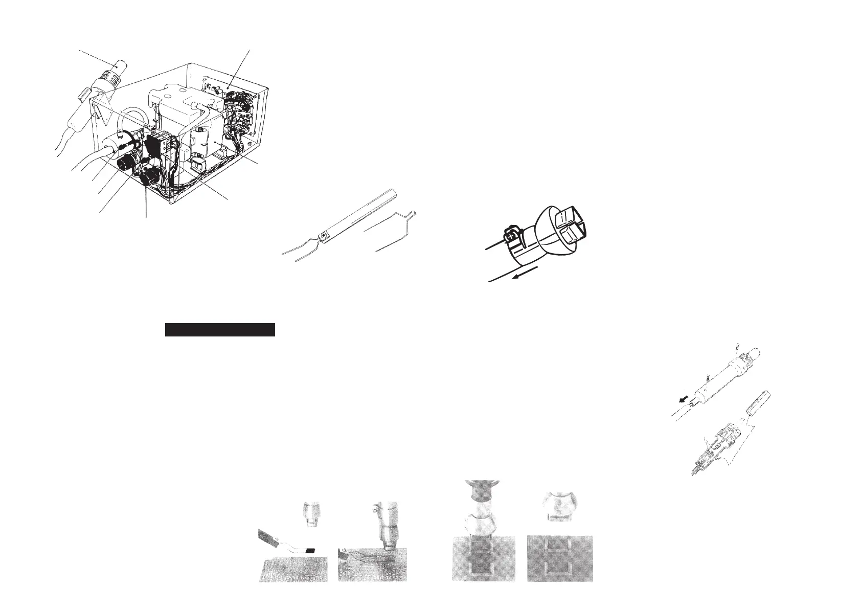
Part Names
FP Pick-up Wire.......1pc
FP Pick-up.......1pc
Air Flow Lamp
Air Flow Control Knob
(Refer to the Temperature
Distribution Chart)
Heater Lamp(Lamp comes
on and off whe the heating
Element gets electricity)
Temperature Control
Knob(Reter to the
temperature Distribtion
Chart)
Power Switch(By turning
on this switch,the Heating
Element begins to warm up
and unit start sending air.)
Pump
P.W.B
Iron
1.Select the FP Pick-up Wire that
matches the size of the IC.
The FP Pick-up has an S wire(14mm) attached to it,but
an L wire (30mm) may be necessary,depending on the
size of the IC.Choose the appropriate wire for the IC.
2.Select the Nozzle that matches the
size of the IC.
Attach the Nozzle when both the pipe and the Nozzle
are cool should neither be warm,check to make sure
that the Temperature Control knob is set to 1stage.
1.Loosen the screw on the Nozzle.
2.Attach the Nozzle as shown in the drawing.Do not
force the Nozzle or pull on the edge of the Nozzle by
pliers.Also, do not stubborn the screw too tightly
Attaching the Nozzle.
Before Operation
1.Thermal Protector
For safety,power is automatically shut off should the unit exceed a
certain temperature.Once the temperature has dropped to a safety
level,power is automatically turned on.Turn off the switch and cool
the iron.After that, to continue operation,reduce the temperature
setting or increase the air flow.Should the Thermal protector be
lripped and you do continue the operation or if you leave that place,
be sure to rurn the power Switch off.
2.Cauton-High Temperature Operation
Do not use the 850 unit near ignitable gases,paper,or other
inflammable materials.Both the nozzle and the heated air are
extremely hot and can cause serions burns.Never touch the heater
pope or allow the heated air to blow against your skin,Initially,the
iron may emit white smoke,but this will soon disappear.
3.After use,besure to cool the unit.
After turning off the power switch,the unit will automatically blow
cool air through the pipe for a short period of time.Do not disconnect
the plug during this cooling process.
4.Never drop or sharply jolt the unit.
The pipe contains quartz glass which will be broken ba your own
break if the unit is dropped or jolted sharply.
5.Do not disassemble the pump.
6.Disconnect the plug when you don't use the
unit for a long time.
When the power cord is connected into the power supply, the unit
has a little flow if electrify, even the power Switch is in off position.
So when you don't use the unit for a long time,please disconnect
the plug.
Precautions
1.Plug the power cord into the power supply.
After connection, the automatic blowing function will start sending air through the pipe, but the Heating Element remains cool.
2.Turn the Power switch on
The Power Switch may be turned on at any time while the automatic blowing function is operating , once the Power Switch is turned on,
the Heating Element will begin to warm up.
3.Adjust the Air Flow and Temperature Control Knobs.
After adjusting the Air Flow and Temperature Control Knob,wait for the temperature to stabilize for a short period of time. Refer to the
0
temperature distribution chart.For your reference,We recommend you to adjust the temperature around 300 to 350 C.As for Air Flow
in case of single nozzle, set the knob 1-3,in another nozzle,set it from 4-6.When using a single nozzle, never set the Temperature
control knob to higher than 6.
4.Place the FP Pick-up under the IC lead.
Slip the FP Pick-up Wire under he IC lead.If the width of the IC does not match the size of the FP Pick-up,adjust the width of the wire
by supressing the wire.
5.Melt the solder.
Hold the iron so that the Nozzle is located directly over,but not touching the IC,and allow the hot air to melt the solder,Be careful
to touch the leads of the lC with the Nozzle.
6.Remove the IC
Once the solder has melted,remove the lC by lifting the FP Pick-up.
7.Turn the Power Switch off.
After the Power Switch is turned off,an automatic blowing function begins
sending cooling air through the pipe in order to cool both the heating
element and the handle,and do not disconnect the plug during this
cooling process.In case you don't use the unit for a long time,please
disconnect the plug.
8.Remove any remaining solder.
After removing the IC,remove remaining solder with a wick or desoldering tool.
Operating Instructions
QFP Desoldering
1.Apply the solder paste.Apply the proper quantity
of solder paste and install the SMD on the PWB.
2.Preheat SMD.Refer to the photo to preheat SMD.
(Fig.1)
3.Soldering.Heat the lead frame evenly.(Fig.2)
4.Washing.When soldering is completed,wash away
the flux.
Note:
While there is merits to solder by hot air,it's also
possible to cause the defects such as solder balls,
solder bridges.We recommend you to examine the
conditions of soldering sufficiently.
1.Remove the screws,slide the tube.Remove the 3 screws(Fig.I-1,2,3)
which secure the handle and slide the cord tube.
2.Open the Handle,Disconnect the ground wire sleeve(Fig.II-1)and
remove the pige.In the quartz glass and heat insulation is installed.Do
not drop or miss it.
3.Remove the Heating Element,Disconnect the terminal(Fig.II-2)and
remove the Heating Element.
4.Insert a new Heating Element,Handle it with care.Never rub the
Heating Element Wire.Insert a new Heating Element and reconnect the
terminal. Reconnect the ground wire after replacing the element.
Assemble the Handle in the reverse order of disassembly.Insert the
Handle's projection into the hole in the pipe.
Replacing the Heating Element
QFP Soldering
Fig.I
Fig.II
1
2
3
2
1
Fig.1Fig.2
Product specificaties
| Merk: | Epcom |
| Categorie: | Soldeermachine |
| Model: | EP-850 |
| Kleur van het product: | Zwart |
| Ingebouwd display: | Nee |
| Gewicht: | 4000 g |
| Breedte: | 187 mm |
| Diepte: | 245 mm |
| Hoogte: | 135 mm |
| Temperatuur (min): | 100 °C |
| Temperatuur (max): | 420 °C |
| Aantal kanalen: | - kanalen |
| Verwarmingsvermogen: | 20 W |
| Ingebouwde luchtpomp: | Ja |
| Pompcapaciteit (luchtpomp): | 23 l/min |
Heb je hulp nodig?
Als je hulp nodig hebt met Epcom EP-850 stel dan hieronder een vraag en andere gebruikers zullen je antwoorden
Handleiding Soldeermachine Epcom

6 Januari 2024
Handleiding Soldeermachine
Nieuwste handleidingen voor Soldeermachine
6 April 2026
8 Maart 2026
7 Maart 2026
7 Maart 2026
5 Maart 2026
5 Maart 2026
5 Maart 2026
3 Maart 2026
27 Februari 2026
25 Februari 2026