Dormakaba HSW-GP Handleiding
Dormakaba Niet gecategoriseerd HSW-GP
Bekijk gratis de handleiding van Dormakaba HSW-GP (18 pagina’s), behorend tot de categorie Niet gecategoriseerd. Deze gids werd als nuttig beoordeeld door 50 mensen en kreeg gemiddeld 4.6 sterren uit 3 reviews. Heb je een vraag over Dormakaba HSW-GP of wil je andere gebruikers van dit product iets vragen? Stel een vraag
Pagina 1/18
DORMA-Glas800.52.069.6.32Stand/Issue 02/03Seite/Page 1/9
HSW-GP Installation instructions
Note: The as-delivered condition is indicated in the manufacturing drawing enclosed.
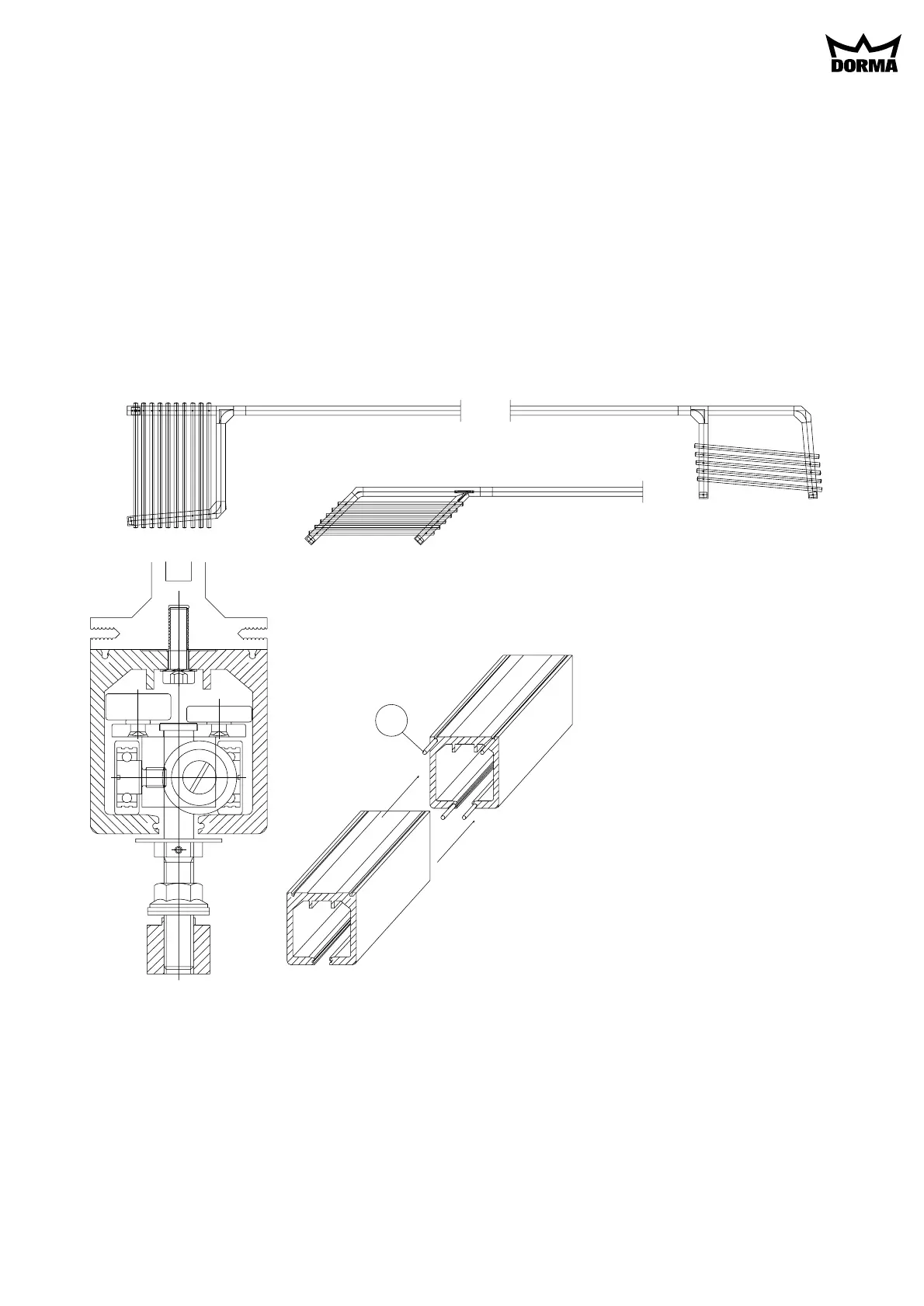
1. Ceiling substructure for track rail and installation of the track rail:
The track rail must be bolted over its entire length (including the stacking track area) to a correctly
aligned horizontal (longitudinally and transversely) ceiling steel substructure (e.g. DORMA substructure
system).
The steel substructure should be designed to accommodate the total weight of all the panels both in the
stacking area and in the partition section. The fixing point intervals for the track rail should be approx.
300 mm along the straight sections and approx. 100 mm in the stacking area.
Caution:All the track joints (except the maintenance end piece, Section 5, page 7) must be provided
with connection pins (a) in order to ensure a flush transition between the track sections and thus
smooth sliding panel operation.
(Fig. 1)
a
Fig. 1
2. Mounting the glass panel fittings (Fig. 2A):
A
Mounting the single-point fixings to the glass:
Insert clamping collar (2) together with the tapered countersunk fastener (1) in the glass bore.
Place the intermediate layer (3) in the nut (4) and screw the nut onto the countersunk fastener. Using
the special wrench, pre-assemble and then tighten with a torque wrench (tightening torque = 15 Nm).
Product specificaties
| Merk: | Dormakaba |
| Categorie: | Niet gecategoriseerd |
| Model: | HSW-GP |
Heb je hulp nodig?
Als je hulp nodig hebt met Dormakaba HSW-GP stel dan hieronder een vraag en andere gebruikers zullen je antwoorden
Handleiding Niet gecategoriseerd Dormakaba

19 September 2023
19 September 2023
19 September 2023
19 September 2023
9 Juli 2023
9 Juli 2023
9 Juli 2023
9 Juli 2023
9 Juli 2023
9 Juli 2023
Handleiding Niet gecategoriseerd
Nieuwste handleidingen voor Niet gecategoriseerd
23 Juli 2026
23 Juli 2026
23 Juli 2026
23 Juli 2026
23 Juli 2026
22 Juli 2026
22 Juli 2026
22 Juli 2026
22 Juli 2026
22 Juli 2026