Dormakaba ES72F Handleiding
Bekijk gratis de handleiding van Dormakaba ES72F (1 pagina’s), behorend tot de categorie Niet gecategoriseerd. Deze gids werd als nuttig beoordeeld door 48 mensen en kreeg gemiddeld 4.9 sterren uit 5 reviews. Heb je een vraag over Dormakaba ES72F of wil je andere gebruikers van dit product iets vragen? Stel een vraag
Pagina 1/1
INSTALLATION
ES72F
Electric Strikes
© 2019 dormakaba USA Inc
DORMA DRIVE, DRAWER AC, REAMSTOWN, PA 17567 PHONE: (800) 523-8483 (717) 336-3881 FAX: (717) 336-2106
EMAIL: archdw.us@dormakaba.comdormakaba.us WEBSITE:
MOUNTING & WIRING INSTRUCTION
1. Determine the vertical centerline of the door lock face
and the horizontal centerline of the latch.
When determining the horizontal centerline IMPORTANT:
observe the following:
Align the angled ramps of the lip FOR MORTISE LOCKS:
bracket with the deadlock trigger of the mortise latch.
Align the center of the latch FOR CYLINDRICAL LOCKS:
with the center of the strike opening. **
2. Transfer both the horizontal and vertical centerlines to
the door frame.**
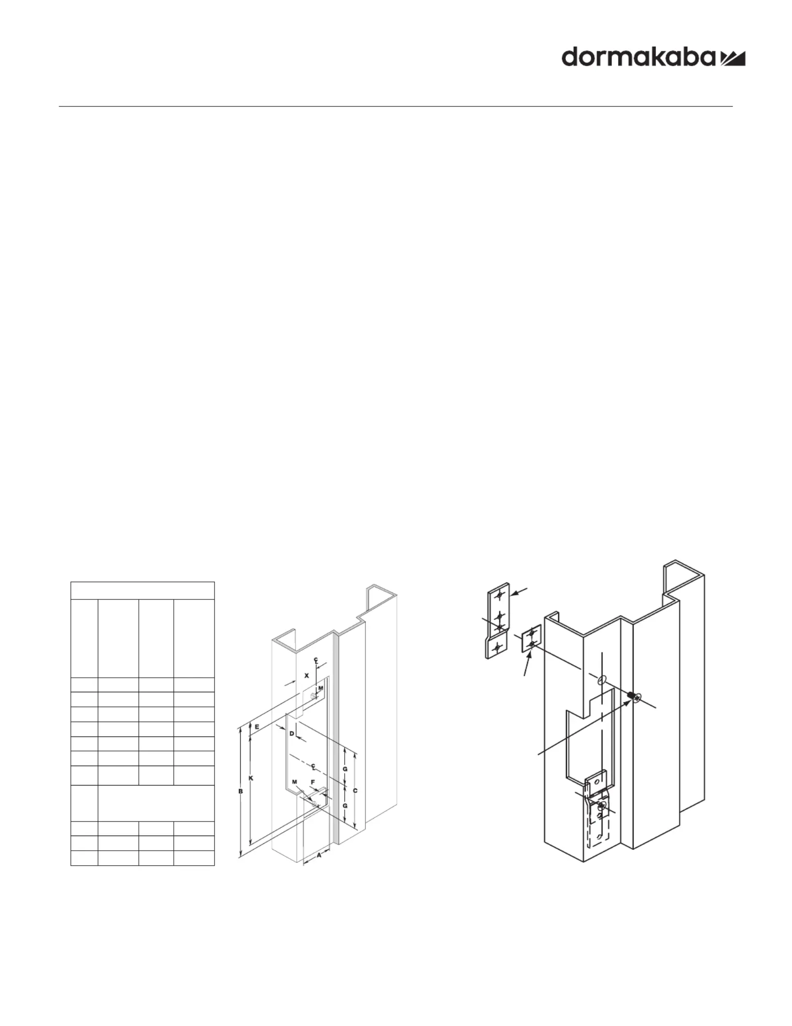
3. Prepare the door frame for cutting as shown below.
4. If required, install the optional “no weld” mounting tabs.
5. Connect the incoming wiring from the power supply to
the terminal screws on the strike insert. DORMA door
strikes are not polarity sensitive, although be certain
to observe proper polarity if a suppression diode is
required for access control applications.
To meet BHMA A156.31 install the MOV provided
across the red and black power wires.
6. Install the door strike in the door frame using the screws
provided.
ISES72F
08281390
PCN18035
R09-19GR
NOTE: Specifications subject to change without notice.
* Dimension F is measured from face of mounting tab to face of frame.
** Dimension X on the drawing is determined by the vertical centerline of the door. If the latch incorporates a deadlocking pin,
additional steps will be necessary to ensure proper operation of the deadlocking pin. Measure the thickness of the deadlocking
pin and add this thickness to Dimension X to relocate the vertical centerline an appropriate distance on the frame.
ES72F
MEASUREMENT
FRACTIONAL
INCHES
DECIMAL
INCHES
METRIC
mm
A1-1/4”1.25031.75
B4-7/8”4.875123.83
C3-3/8”3.37585.73
D29/32”.90623.02
E3/8”.3759.53
F1/8”.1253.18
G1-11/16”1.68842.86
X
Vertical Centre Line of Door
Lock and Mounting Face
Plate
K4-1/8”4.125104.78
M12-24N/AN/A
Dpth1-1/2”1.538
MOUNTING TAB KIT INSTRUCTIONS
Mounting tab kit is for use with aluminum and steel frames that
do not have factory installed mounting tabs for electric strike
installation.
1. Prepare the frame as shown. Fasten the mounting tabs to
the faceplate of the strike, selecting the appropriate shims
for your installation.
2. Using the assembled strike and tabs as a template, place
against the frame and mark the mounting hole locations.
Remove and drill two 3/16” holes in the frame for each
mounting tab and countersink the frame.
3. Remove the tabs from the faceplate and install in the frame
using the 12-24 x 3/8” machine screws supplied. Tabs are
zinc plated and drilled and tapped for this purpose.
4. Make final electrical connections as notes at left and mount
strike to the tabs with the 12-24 x 3/8” machine screws.
Frame
Self-Adhesive
Mounting
Shim (8 incl.)
Mounting bTa
(2 incl.)
12-24 Machine
Screws (2 each to
keep tab straight)
Product specificaties
| Merk: | Dormakaba |
| Categorie: | Niet gecategoriseerd |
| Model: | ES72F |
Heb je hulp nodig?
Als je hulp nodig hebt met Dormakaba ES72F stel dan hieronder een vraag en andere gebruikers zullen je antwoorden
Handleiding Niet gecategoriseerd Dormakaba

19 September 2023
19 September 2023
19 September 2023
19 September 2023
9 Juli 2023
9 Juli 2023
9 Juli 2023
9 Juli 2023
9 Juli 2023
9 Juli 2023
Handleiding Niet gecategoriseerd
Nieuwste handleidingen voor Niet gecategoriseerd
23 Juli 2026
23 Juli 2026
23 Juli 2026
23 Juli 2026
23 Juli 2026
23 Juli 2026
23 Juli 2026
23 Juli 2026
23 Juli 2026
22 Juli 2026