Dito Sama 602068 Handleiding
Dito Sama
Snijmachine
602068
Bekijk gratis de handleiding van Dito Sama 602068 (8 pagina’s), behorend tot de categorie Snijmachine. Deze gids werd als nuttig beoordeeld door 4 mensen en kreeg gemiddeld 4.9 sterren uit 2.5 reviews. Heb je een vraag over Dito Sama 602068 of wil je andere gebruikers van dit product iets vragen? Stel een vraag
Pagina 1/8

Fault nding 6
Maintenance 7
Compliance with regulations 8
Contents
Presentation 1
Installation 1
Using and safety 3
Cleaning, hygiene and storage 5
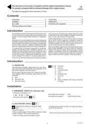
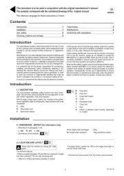
1. DESCRIPTION1
• This universal vegetable preparation machine may be used
for cutting, slicing, shredding, grating, making chips and dicing.
Its range of assorted cutting equipment provides high rates of
output and its two interchangeable feed hoppers which adapt to
the user’s requirements make the TR300 the professional vege-
table preparation machine for catering and the food industry alike.
A Stainless steel casing
B Storage space
C Body
D Hopper support cover
E Automatic hopper
F Electric controls
G Locking lever
1. TECHNICAL DESCRIPTION2
This vegetable preparation machine consists essentially of the
following:
• A stainless steel casing on castors containing:
- The motor and the electrical controls,
- A storage space for the cutting equipment, located in the lower
part.
•
A cast aluminium body attached onto the casing, containing:
- The gear reduction mechanism,
- The drive for the cutting and ejection equipment.
• A cast aluminium hopper support cover which is hinged at the
back and locked at the front.
• Two swivelling, interchangeable feed hoppers suited to the
dierent types of work:
- The automatic hopper with a rotating feed-screw controlled by
a geared reducer.
- The special long vegetable hopper which has 9 tubes of die-
rent lengths and diameters.
• Various items of cutting equipment including:
- Slicing, shredding and grating plates of 300 mm diameter with
a standard ejector,
- Dicing grids,
- Chip accessories with rotating cutting discs and a special chip
ejector.
1 TR300 GB 06 2016
Presentation
GB
03/2024
This document is to be used in conjunction with the original manufacturer’s manual.
The symbols correspond with the numbered drawings of the original manual.
1.1
Introduction
The User Manual contains useful information for the user on how
to work correctly and in complete safety, and is designed to make
it easier to use the machine (called «machine» or «appliance»
below).
What follows is in no case intended to be a long list of warnings and
constraints, but rather a series of instructions meant to improve the
service provided by the machine in every respect, and particularly
to avoid a series of injuries or damage to equipment that might
result from inappropriate procedures for use and management.
It is essential that all the people responsible for transporting,
installing, commissioning, using, maintaining, repairing or dis-
mantling the machine should consult this manual and read it
carefully before proceeding with the various operations, in order
to avoid any incorrect or inappropriate handling that might be
result in damage to the machine or put people’s safety at risk.
It is just as important that the Manual should always be available
to the operator and it should be kept carefully where the machine
is used ready for easy and immediate consultation in case of any
doubt, or in any case, whenever the need arises.
If after reading the Manual, there are still any doubts concerning
how to use the machine, please do not hesitate to contact the
Manufacturer or approved After Sales Service provider, who is
constantly available to ensure quick and careful service for im-
proved machine operation and optimum eciency.
Note that the safety, hygiene and environmental protection stan-
dards currently applicable in the country where the machine is
installed must always be applied during all phases of machine
operation. Consequently it is the user’s responsibility to ensure
that the machine is operated and used solely under the optimum
safety conditions laid down for people, animals and property.
Installation
ATTENTION!!
Machine storage: -25°C to +50°C
Ambient temperature during operation: +4°C to +40°C
This machine is for professional use and must be used by sta trained to use, clean and maintain it, in terms or reliability and safety.
Use the machine in adequately lit premises (See applicable technical standard for the country of use. In Europe, refer to standard
EN 12464-1)
When handling the machine, always check that the parts taken hold of are not mobile elements: risk of dropping and injury to the
lower limbs.
The machine is not designed for use in explosive atmospheres.
The machine is delivered without wheels or skids for mounting refer to the installation sheet.
The reference language for these instructions is French.

2.1 DIMENSIONS AND WEIGHT (INDICATION
ONLY)
• Packaged dimensions (L x W x H)
- TR300 motor unit: 840 x 680 x 1300
- Net weight: 98 kg - Packaged weight: 148 kg
- Auto. hopper: 950 x 640 x x720
- Net weight: 40 kg - Packaged weight: 55 kg
- Long Vegetable hopper: 600 x 600 x 750
- Net weight: 22 kg - packaged weight: 24 kg
• Machine dimensions without hopper (mm): 710 x 470 x 1070
• Machine dimensions with auto. hopper (mm):
1020 x 560 x 1520
- Loading height (mm): 1400
• Machine dimensions with long vegetable hopper (mm):
710 x 470 x 1540
- Loading height (mm): 1540
• Handling - Transport
The machine is packaged in such a way as to be lifted with a
fork-lift truck. In the event of manual handling of the machine
alone, two persons will be required.
2.1b
2.1a
Always place the machine on a strong, at, stable support
2. POSITION AND LAYOUT2
This vegetable preparation machine is a oor-standing appliance
which is easy to move thanks to its castors.
• The loading height varies depending on the hopper type.
• Product evacuation height 820 mm from the oor for passage
of an 800 mm container.
• Sucient space will be required around the machine to move
around, taking into account:
- The dimensions of the supply and collection containers
- Any loading and evacuation equipment
- Storage space where more than one hopper is used (console,
shelves, etc…).
• The work position can be laid out in dierent ways by changing
the direction of the hoppers (two positions)
• Where the hopper direction is changed, the safety detector rod
must be moved.
2. 2.1a 1b
2. ELECTRICAL CONNECTIONS3
ATTENTION!!
Connection to the electrical power supply must be done according to proper professional practice by a qualied and authorised
person (see current standards and legislation in the country of installation).
If an adapter is used on the socket, a check must be made that the electrical characteristics of this adapter are not lower than
those of the machine.
Do not use multiple plugs
The AC power supply to the machine must comply with the following conditions EN60204-1;
- Maximum voltage variation: ±10%
- Maximum frequency variation: ±1% on a continuous basis, ± 2% over short periods
ATTENTION: the electrical installation must comply (for design, creation and maintenance) with the legal and standard
requirements in the country where used.
- Check that the electric mains voltage, the value shown on the specication plate.
- The machine’s electrical power supply must be protected against voltage surges (short-circuits and excess voltages) using a
circuit breaker compliant with IEC60947-2 properly sized, of the appropriate gauge relative to the place of installation and machine
specications –
ATTENTION: Concerning protection against indirect contact (depending on the type of power supply provided and
connection of the exposed conductive parts to the equipotential protection circuit), refer to point 6.3.3 of EN 60204-1
(IEC 60204-1) with the use of protection devices for automatic shut-o of power in the event of an insulation fault with
a TN or TT, system, or for the IT system, with the use of a permanent insulation or dierentials controller for automatic
shut-o. The requirements of IEC 60364-4-41, 413.1 must apply for this protection.
For example: in a TN or TT system, a dierential circuit breaker must be installed upline of the power supply, with a
suitable power cut-o (e.g.: 30 mA) on the earthing installation for the place where it is planned to install the machine.
ATTENTION: Failure to comply with these instructions means the customer runs the risk of machine failure and/or acci-
dents due to direct or indirect contacts.
TR300 GB 03 2024 2

- Make a check on correct operation and direction of rotation.
- Ret the plate.
If the voltage of the automatic feed hopper is changed,
Electrical connection of the automatic hopper:
• A geared reducer drives the automatic hopper feed-screw when
the TR300 is switched on. It is connected at the rear of the casing
by a sealed plug and socket supplied (3 phase wires + earth).
• After checking the direction of rotation of the machine drive
shaft, check that the feed-screw is rotating in a clockwise direction.
• If the direction of rotation is incorrect, change over the two
phase wires on the hopper connection.
• In the three phase, 230 - 400 V dual voltage version, the
connection is made in 400 V on leaving the factory. To connect
for use with a 230 V three phase supply, proceed as follows:
- Remove the motor terminal housing.
- Change over the motor terminal plate connections as per the
diagram below.
- Check the operation and the direction of rotation of the feed-
screw (clockwise).
Vegetable preparation machine electrical connections
• First check that the electrical specications on the rating plate
are the same as on the power cable.
• Provide an accessible wall-mounted power outlet standardized
with 3 poles + Ground, rated 20 A compliant with IEC60309, and
a corresponding waterproof plug to be mounted on the power
cord.
The machine must be earthed with a green/yellow wire.
• Motor specications
A Number of phases (3, three-phase)
B Nominal voltage in volts (value and range or commutation)
C Nominal current (Amperes)
D Nominal rating (Watts)
• Mains connection by means of a four-conductor cable (3 phase
wires + earth), to be connected to a sealed plug (not supplied)
with a 20 A fuse.
• Check the direction of rotation of the vertical drive shaft using
the standard ejector tted as standard.
- Unlock the cover and tilt it backwards.
- Fit the ejector and close the cover.
- Press the On button then quickly raise the cover to see which
direction the ejector is turning in. It should be turning in the
clockwise direction.
• If the direction of rotation is incorrect, change over the two
phase wires on the plug.
• In the three phase, 230 - 400 Volt dual voltage version, the
connection is made in 400 V on leaving the factory. To connect
for use with a 230 V three phase supply, proceed as follows:
- Dismantle the front plate of the casing to access the power
supply card.
- Change the voltage for the primary of the transformer on the
power supply card by moving the 400V terminal to 230V.
- Change the motor voltage by moving the connecting strips in
the terminal box.
Using and Safety
For safety reasons, never leave the automatic hopper motor
connected to a plug other than the machine plug.
2.3a
2.3b
2.3d
To PAT test the Electrolux Range of Food Preparation Equipment,
the PCB board needs to be disconnected before any test is done.
This is due to the fact that the boards are tted with a grounding
diode that can give incorrect result during such a test. Also on a
standard appliance a ash test of 25 amps and up to 3000v is
used but, as you would expect, to use this on equipment, which
has a printed circuit, board would be quite destructive to that
board. We would recommend the use of a PAT tester approved
for computer systems which use a lower rate of amps.
The appliance is perfectly safe and is CE certicated. There are
two ways to get overcome this problem.
· Disconnect the board as instructed and test using test for PC’s,
· Or install the mixer on a fused spur (no plug) as this takes it
away from being a portable appliance and the PAT test is then
not needed.
Clean the machine properly prior to its rst use
This machine is for professional use and must be used by sta trained to use, clean and maintain it, in terms or reliability and safety.
Use the machine in adequately lit premises (See applicable technical standard for the country of use. In Europe, refer to standard
EN 12464-1)
When handling the machine, always check that the parts taken hold of are not mobile elements: risk of dropping and injury to the
lower limbs.
Uncontrolled closure of the lid or ram press involves a risk of crushing the ngers.
Never put a hand in the ejection area while the machine is in operation; risk of injury. It is strictly forbidden to put the safety systems
out of action or modify them: Risk of permanent injury!!!!
Check that the safety devices operate correctly each time before using (see paragraph on «safety system adjustments»).
Never put a hand, a hard or frozen object in the appliance
For health and safety reasons, always use a washable or disposable strong head covering that covers the hair completely.
ATTENTION: All operations, whether using, cleaning or maintenance, present risks of cuts; never force and always keep
hands a reasonable distance from cutting edges.
Always use appropriate protective equipment when carrying out these operations.
The machine is not designed for use in explosive atmospheres.
ATTENTION !!
3 TR300 GB 03 2024
Product specificaties
| Merk: | Dito Sama |
| Categorie: | Snijmachine |
| Model: | 602068 |
Heb je hulp nodig?
Als je hulp nodig hebt met Dito Sama 602068 stel dan hieronder een vraag en andere gebruikers zullen je antwoorden
Handleiding Snijmachine Dito Sama
12 Augustus 2025
12 Augustus 2025
12 Augustus 2025
11 Augustus 2025
11 Augustus 2025
11 Augustus 2025
11 Augustus 2025
11 Augustus 2025

11 Augustus 2025
11 Augustus 2025
Handleiding Snijmachine
- Wilfa
- Bosch
- Ernesto
- G3 Ferrari
- Berkel
- RGV
- Tescoma
- Presto
- Enkho
- CaterChef
- Mia
- Quigg
- Louis Tellier
- Domo
- Philco
Nieuwste handleidingen voor Snijmachine
11 Augustus 2025
11 Augustus 2025
11 Augustus 2025
11 Augustus 2025
11 Augustus 2025
11 Augustus 2025
11 Augustus 2025

11 Augustus 2025
11 Augustus 2025
11 Augustus 2025