Crestron TSW-732-W-S Handleiding


Lees hieronder de đź“– handleiding in het Nederlandse voor Crestron TSW-732-W-S (2 pagina's) in de categorie Niet gecategoriseerd. Deze handleiding was nuttig voor 55 personen en werd door 2 gebruikers gemiddeld met 4.5 sterren beoordeeld

Pagina 1/2
DO GUIDE
DO Check the Box
QUANTITY PRODUCT COLOR PART NUMBER
1 Bit, Torx, T8 2025915
1 Cover, Plastic, No Buttons, Left Side, 4.5"x 1" x 0.625"
1Black 2033452
1 Cover, Plastic, No Buttons, Left Side, 4.5" x 1" x 0.625"
2White 2033451
1 Cover, Plastic, No Buttons, Right Side, 4.5" x 1" x 0.625"
1Black 2033450
1 Cover, Plastic, No Buttons, Right Side, 4.5" x 1" x 0.625"
2White 2033449
2 Screw, 4B x 3/4", Flat Head, Phillips 2019088
2 Screw, 4-40 x 1/4", Undercut Head, Phillips1Black 2007152
2 Screw, 4-40 x 1/4", Undercut Head, Phillips22007160
2 Screw, 4-40 x 1/4", Flat Head, Torx1Black 2025311
2 Screw, 4-40 x 1/4", Flat Head, Torx22025312
4 Screw, 6-32 x 1-1/2", Flat Head, Phillips 2031703
1. This part ships with the TSW-732-B-S.
2. This part ships with the TSW-732-W-S.
TSW-732
7” Room Scheduling Touch Screen
DO Change the Button Inserts or Button Covers
The Crestron® TSW-732 Touch Screen ships with 10 “hard key” push buttons for quick access to
commonly used functions. Optional, custom engravable button covers are available (TSW-730-BTNO
and custom engraving sold separately). For a clean appearance, either column of buttons may be
removed and covered using the included no-button covers.
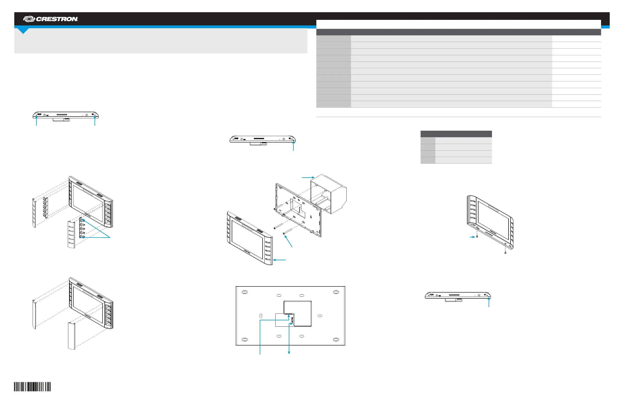
To change the inserts or covers, use the following procedure:
1. Insert a small at head screwdriver into the appropriate hole on the bottom of the TSW-732 to
release its cover.
2. Gently remove the cover from the TSW-732.
3. If removing the button insert after removing the button cover, use a small at head screwdriver
to press the tabs, and then gently lift the button insert from the TSW-732. Refer to the following
illustration for the tab locations on the button insert.
Touch Screen with Button Inserts
4. Carefully position the new cover over the front of the touch screen and press it into place.
Touch Screen with No-Button Covers
DO Install the Touch Screen
The TSW-732 can be mounted into a standard
electrical box or onto a at surface. A tabletop
enclosure and swivel mount (TSW-730-TTK and
SMK-4SM/730, both sold separately) are also
available.
Mounting into a U.S. Electrical Box
To mount the TSW-732 into a U.S. electrical box,
use the following procedure:
1. Insert a small at head screwdriver into the
hole shown in the following illustration, and
gently separate the back panel from the touch screen.
2. Use the four included 6-32 x 1-1/2" screws to attach the back panel to the electrical box.
3. Make connections to the TSW-732 using Crestron power supplies for Crestron equipment.
4. Carefully position the front of the touch screen over the back panel and gently snap it into place.
5. Use two of the included 4-40 x 1/4" screws to secure the TSW-732. For standard applications,
use the Phillips screws. For secure applications, use the security type Torx screws along with
the included Torx screwdriver bit.
Mounting into a U.K. Electrical Box
To mount the TSW-732 into a U.K. electrical box, use the following procedure:
1. Insert a small at head screwdriver into the hole shown in the following illustration, and gently
separate the back panel from the touch screen.
Insert a screwdriver to release the covers.
Use a screwdriver
to release
the button insert.
Insert a screwdriver to separate the back panel.
U.S. Electrical Box
TSW-732
Screws (4) 6-32 x 1-1/2"
Occupancy Sensor Input:
From Room Occupancy Sensor
LAN PoE:
10BASE-T / 100BASE-TX
Ethernet to LAN
Screws (2) 4-40 x 1/4" Phillips
or
Screws (2) 4-40 x 1/4" Torx
Insert a screwdriver to separate the back panel.
PIN DESCRIPTION
G Ground
2 Occupancy sensor #2 status
1 Occupancy sensor #1 status
24 24 Vdc power
DO GUIDE DOC. 7668B (2040919) 09.15
Specications subject to change without not ice.
2. Use the two included 4B x 3/4" screws to attach the back panel to the electrical box.
3. Make connections to the TSW-732 using Crestron power supplies for Crestron equipment.
4. Carefully position the front of the touch screen over the back panel and gently snap it into place.
5. Use two of the included 4-40 x 1/4" screws to secure the TSW-732. For standard applications,
use the Phillips screws. For secure applications, use the security type Torx screws along with the
included Torx screwdriver bit.
DO Access the Setup Screens
NOTE: The TSW-732 can take up to 120 seconds to boot.
The setup screens enable basic conguration prior to regular operation of the TSW-732. To display
the main setup screen, touch the screen while applying power to the unit.
NOTE: If no project has been loaded or if an invalid project has been loaded, the touch screen
defaults to the main setup screen.
During regular operation of the touch screen, there are two ways to activate the setup functions:
1. Place a button on the project main page, and assign the reserved join number (17242) that
activates setup.
2. Press hard keys 1, 2, 3, and 4 on the left side of the touch screen display in sequence, twice
(press 1, 2, 3, 4, 1, 2, 3, 4) within a 5-second period.
The main setup screen is displayed.
As of the date of manufacture, the product has been tested and found to comply with specications for CE marking.
Federal Communications Commission (FCC) Compliance Statement
This device complies with part 15 of the FCC Rules. Operation is subject to the following two conditions:
(1) This device may not cause harmful interference, and (2) this device must accept any interference received, including interference that may cause undesired operation.
CAUTION: Changes or modications not expressly approved by the manufacturer responsible for compliance could void the user’s authority to operate the equipment.
NOTE: This equipment has been tested and found to comply with the limits for a Class B digital device, pursuant to part 15 of the FCC Rules. These limits are designed to provide reasonable protection
against harmful interference in a residential installation. This equipment generates, uses and can radiate radio frequency energy and, if not installed and used in accordance with the instructions, may
cause harmful interference to radio communications. However, there is no guarantee that interference will not occur in a particular installation.
If this equipment does cause harmful interference to radio or television reception, which can be determined by turning the equipment off and on, the user is encouraged to try to correct the interference
by one or more of the following measures:
• Reorient or relocate the receiving antenna.
• Increase the separation between the equipment and receiver.
• Connect the equipment into an outlet on a circuit different from that to which the receiver is connected.
• Consult the dealer or an experienced radio/TV technician for help.
Industry Canada (IC) Compliance Statement
CAN ICES-3(B)/NMB-3(B)
Crestron product development software is licensed t o Crest ron dealers and Crestron Service Providers (CSPs) under a limited non-exclusive, non-t ransferable Software Development Tools License Agreement. Crestron product operating system sof tware is licensed t o Crest ron dealers, CSPs, and
end-users under a separate End-User License Agreement. Both of these Agreement s can be found on t he Crestron website at www.crestron.com/legal/software_license_agreement.
The specic patents t hat cover Crestron products are listed at patents.crest ron.com The product warranty can be found at www.crestron.com/warrant y.
Certain Crestron products cont ain open source sof t ware. For specic information, please visit . www.crestron.com/opensource
Crestron and the Crestron logo are either trademarks or registered trademarks of Crestron Elect ronics, Inc., in the Unit ed States and/or other countries. Other trademarks, registered trademarks, and t rade names may be used in this document to refer to either the ent ities claiming the marks and
names or th eir products. Crest ron disclaims any proprietary interest in the marks and names of others. Crestron is not responsible f or errors in typography or photography.
This document was written by the Technical Publicat ions depart ment at Crest ron.
©2015 Crestron Electronics, Inc.
DO Learn More
Visit the website for additional information and the latest rmware updates. To learn more
about this product, use a QR reader application on your mobile device to scan the QR
image.
Crestron Electronics
15 Volvo Drive, Rockleigh, NJ 07647
888.CRESTRON | www.crestron.com
4
3
1
2
Occupancy Sensor Input:
From Room Occupancy Sensor
LAN PoE:
10BASE-T / 100BASE-TX
Ethernet to LAN
Screws (2) 4-40 x 1/4" Phillips
or
Screws (2) 4-40 x 1/4" Torx
U.K. Electrical Box
TSW-732
Screws (2) 4B, 3/4"
PIN DESCRIPTION
G Ground
2 Occupancy sensor #2 status
1 Occupancy sensor #1 status
24 24 Vdc power


Product specificaties

Merk: Crestron
Categorie: Niet gecategoriseerd
Model: TSW-732-W-S

Heb je hulp nodig?

Als je hulp nodig hebt met Crestron TSW-732-W-S stel dan hieronder een vraag en andere gebruikers zullen je antwoorden


Handleiding Niet gecategoriseerd Crestron

Handleiding Niet gecategoriseerd

Nieuwste handleidingen voor Niet gecategoriseerd