Crestron Green Light GL-EXP-DIMU-DALI Handleiding
Crestron Niet gecategoriseerd Green Light GL-EXP-DIMU-DALI
Bekijk gratis de handleiding van Crestron Green Light GL-EXP-DIMU-DALI (2 pagina’s), behorend tot de categorie Niet gecategoriseerd. Deze gids werd als nuttig beoordeeld door 36 mensen en kreeg gemiddeld 4.3 sterren uit 3 reviews. Heb je een vraag over Crestron Green Light GL-EXP-DIMU-DALI of wil je andere gebruikers van dit product iets vragen? Stel een vraag
Pagina 1/2
GL-EXP-DIM-DALI/GL-EXP-DIMU-DALI/GL-EXP-DIMFDB-DALI/GL-EXP-DIMFLV-DALI/GL-EXP-SW-DALI
Crestron Green Light
®
Expansion Module, DALI
®
Installation & Operation Guide
Description
The GL-EXP-DIM-DALI, GL-EXP-DIMU-DALI, GL-EXP-DIMFDB-DALI,
GL-EXP-DIMFLV-DALI, and GL-EXP-SW-DALI are independent Crestron Green Light
®
expansion modules that are controlled by DALI
®
and provide one channel of control for a
variety of lighting loads. A single module supports 120 volt or 277 volt loads up to 16
amps.
The Crestron
®
GL-EXP-DIM-DALI, GL-EXP-DIMU-DALI, GL-EXP-DIMFDB-DALI,
GL-EXP-DIMFLV-DALI, and GL-EXP-SW-DALI share common features and functions and
will be referred to as “GL-EXP-*-DALI” except where noted.
The specications for the GL-EXP-*-DALI are listed below.
Specications
Additional Resources
Visit the product page on the Crestron website (www.crestron.com)
for additional information and the latest rmware updates.
5 13/16 in
(147 mm)
5/16 in
(9 mm)
8 5/16 in
(211 mm)
7 5/16 in
(186 mm)
8 5/8 in
(219 mm)
8 3/4 in
(223 mm)
1/2 in
(13 mm)
6 3/8 in
(163 mm)
5 1/16 in
(129 mm)
3 13/16 in
(81 mm)
2 in
(52 mm)
Typ
1 13/16 in
(46 mm)
3 1/16 in
(78 mm)
(2x) Ø3/16 in
(5 mm)
(2x)
Ø3/18 in
(10 mm)
(2x) Ø1/4 in
(7 mm)
(1 1/2 in
(39 mm)
Double Ring Knockout for 1/2 in and 3/4 in
conduit Ø.875 and Ø1.125 in after knockout
removal (typ).
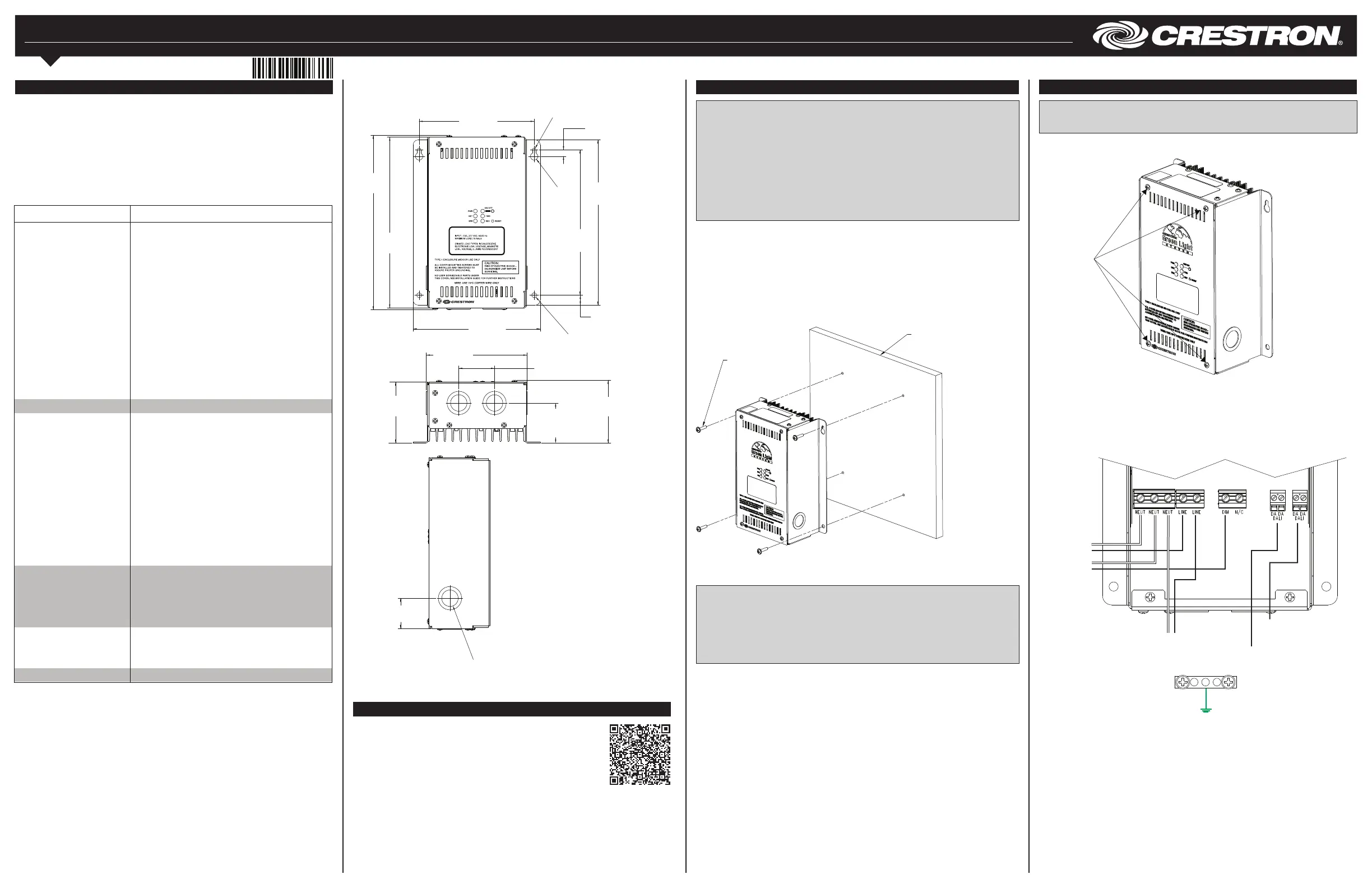
GL-EXP-DIMU-DALI
2. Wire the device as shown below. An additional LINE, NEUT, and GND connection is
supplied for power to pass through. Keep the following in mind while wiring:
• Wires should be 10 to 24 AWG.
• Wires should be stripped to 5/16 in (8 mm).
• Tighten the terminal screws to 4.5 in-lbs (0.5 Nm).
Wire the GL-EXP-DIM-DALI
Wiring Diagrams
WARNING: RISK OF SERIOUS PERSONAL INJURY. Turn off power at the circuit
breaker(s) prior to installation. Installing with power on can result in serious personal
injury and damage to the device.
1. Use a #2 Phillips screwdriver to remove the cover screws and remove the cover.
Remove Cover Screws
Installation
WARNING: To avoid re, shock, or death, turn off the power at the circuit breaker(s) or
fuse and test that power is off before wiring!
NOTES: Observe the following points:
• This product must be installed and used in accordance with the appropriate electrical
codes and regulations.
• This product must be installed by a licensed electrician.
• Use 75°C copper wire or better.
NOTE: Before using the GL-EXP-*-DALI, ensure the device is using the latest rmware.
Check for the latest rmware for the GL-EXP-*-DALI at www.crestron.com/rmware.
Firmware is loaded onto the device using Crestron Toolbox™.
Preparing and Connecting DALI and 0-10V Ports
Strip the ends of the wires approximately 7/16 in (11 mm). Use care to avoid nicking the
conductors. Tighten the connector to 5 in-lb (0.5 to 0.6 N-m). The wire gauge should be 14
to 26 AWG.
Installation
The GL-EXP-*-DALI is mounted to any vertical surface using four screws. The screws must
be appropriate for the mounting surface.
Installing the GL-EXP-*-DALI Module
NOTE: To prevent potential heat damage to the drywall, do not mount the
GL-EXP-*-DALI directly onto drywall. Mount the GL-EXP-*-DALI to a piece of plywood
that is at least 1/2 in (13 mm), and then mount the GL-EXP-*-DALI and plywood to the
drywall.
NOTE: To ensure proper ventilation, the device must be installed vertically on a vertical
surface. Install the device with 6 in (153 mm) of clearance from the top and bottom of the
device.
Mounting Surface
#8 Mounting
Screws Qty. 4
(Not Supplied)
Cover
Screws
The dimensions for the GL-EXP-*-DALI are shown in the following illustrations.
GL-EXP-*-DALI Dimensions
SPECIFICATION DETAILS
Load Ratings
Channels 1
Load Rating 16 A
Dimmed Load Types
GL-EXP-DIM-DALI:
Incandescent, magnetic low-voltage, 2-wire
dimmable uorescent
GL-EXP-DIMU-DALI:
Incandescent, electronic low-voltage, magnetic low-
voltage, 2-wire uorescent
GL-EXP-DIMFDB-DALI:
3-wire uorescent
GL-EXP-DIMFLV-DALI:
0-10 V fluorescent, 0-10 V LED
Switched Load Types
GL-EXP-SW-DALI:
Incandescent, magnetic low-voltage, electronic low-
voltage, HID, uorescent ballast
Input Voltage 100 to 277 Vac, 50/60 Hz
Indicators
PWR
Green LED indicates line power is applied to the LINE
terminal.
ON/OFF Red LED indicates power is applied to the load.
NET Yellow LED indicates network communication.
ERR Red LED blinks to indicate an error condition. Refer to
“Error States” for additional information.
FWD
(GL-EXP-DIMU-DALI
Only)
Red LED shows that the unit is operating in forward-
phase mode.
REV
(GL-EXP-DIMU-DALI
Only)
Red LED shows that the unit is operating in reverse-
phase mode.
Controls
ON/OFF Pushbutton toggles power to the load. Press and hold
the pushbutton to dim the load up and down
(dimming models only).
RESET Pushbutton initiates hardware reset.
Environmental
Temperature 32° to 104° F (0° to 40° C)
Humidity 10% to 90% RH (non-condensing)
Weight 3.4 lb (1.6 kg)
Pass Through to
Additional
Module
From Circuit
Breaker
To Dimmed
Load
From DALI
Network
To Additional
DALI Modules
Product specificaties
| Merk: | Crestron |
| Categorie: | Niet gecategoriseerd |
| Model: | Green Light GL-EXP-DIMU-DALI |
Heb je hulp nodig?
Als je hulp nodig hebt met Crestron Green Light GL-EXP-DIMU-DALI stel dan hieronder een vraag en andere gebruikers zullen je antwoorden
Handleiding Niet gecategoriseerd Crestron

26 Mei 2026
7 Maart 2026
4 Maart 2026
28 Januari 2026
27 Januari 2026
4 December 2025
3 December 2025
2 December 2025
2 December 2025
2 December 2025
Handleiding Niet gecategoriseerd
Nieuwste handleidingen voor Niet gecategoriseerd
24 Juli 2026
24 Juli 2026
23 Juli 2026
23 Juli 2026
23 Juli 2026
23 Juli 2026
23 Juli 2026
23 Juli 2026
23 Juli 2026
23 Juli 2026