Bosch Condens 5000W Handleiding

Bosch Heater Condens 5000W

Lees hieronder de 📖 handleiding in het Nederlandse voor Bosch Condens 5000W (64 pagina's) in de categorie Heater. Deze handleiding was nuttig voor 96 personen en werd door 2 gebruikers gemiddeld met 4.5 sterren beoordeeld

Pagina 1/64
6 720 646 195 (2018/10) AU/NZ
Installation and Maintenance Instructions
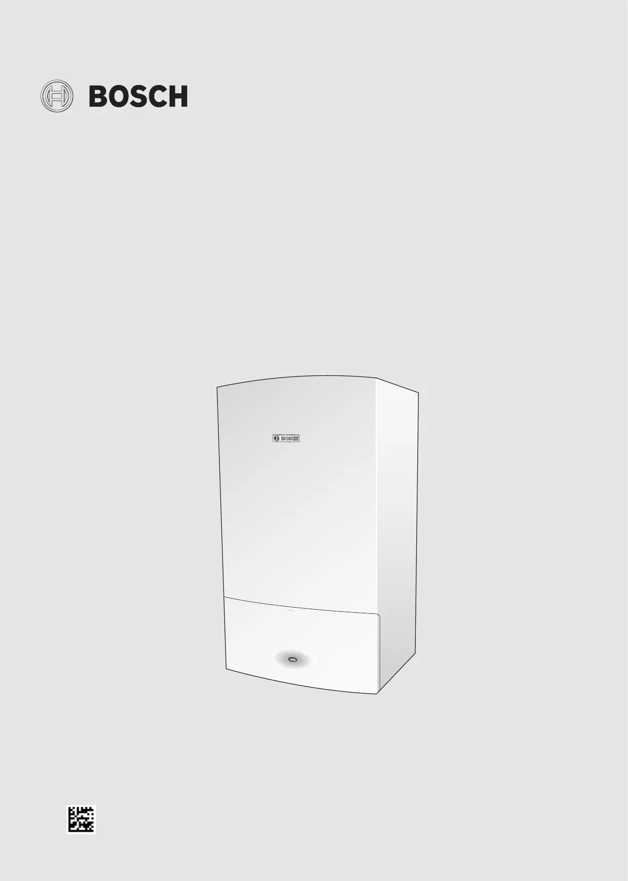
Hydronic gas system boiler 18kW
Bosch Condens 5000W
6720646195-00.1Wo
ZSB18 - 2A
Table of contents
Bosch Condens 5000W – 6 720 646 195 (2018/10)
2
Table of contents
1 Explanation of symbols and safety instructions . . . . . . . . . . . 3
1.1 Explanation of symbols . . . . . . . . . . . . . . . . . . . . . . . . . . 3
1.2 General safety instructions . . . . . . . . . . . . . . . . . . . . . . . 3
2 Product Information . . . . . . . . . . . . . . . . . . . . . . . . . . . . . . . . . . 5
2.1 Boiler carton contents . . . . . . . . . . . . . . . . . . . . . . . . . . . 6
2.2 Technical data. . . . . . . . . . . . . . . . . . . . . . . . . . . . . . . . . . 7
2.3 Layout . . . . . . . . . . . . . . . . . . . . . . . . . . . . . . . . . . . . . . . . 8
3 Pre-Installation. . . . . . . . . . . . . . . . . . . . . . . . . . . . . . . . . . . . . . 11
3.1 Cleaning primary systems . . . . . . . . . . . . . . . . . . . . . . . 11
3.2 Mains supply. . . . . . . . . . . . . . . . . . . . . . . . . . . . . . . . . . 11
3.2.1 Electrical supply . . . . . . . . . . . . . . . . . . . . . . . . . . . . . . . 11
3.2.2 Equipotential (earth) bonding. . . . . . . . . . . . . . . . . . . . 11
3.2.3 Gas supply . . . . . . . . . . . . . . . . . . . . . . . . . . . . . . . . . . . 11
3.3 Water system and pipe work . . . . . . . . . . . . . . . . . . . . . 11
3.4 Condensate pipe work . . . . . . . . . . . . . . . . . . . . . . . . . . 13
3.4.1 Internal connections . . . . . . . . . . . . . . . . . . . . . . . . . . . 13
3.5 Pressure relief drain line . . . . . . . . . . . . . . . . . . . . . . . . 14
3.6 Boiler location and clearances . . . . . . . . . . . . . . . . . . . 15
3.6.1 Installation location . . . . . . . . . . . . . . . . . . . . . . . . . . . . 15
3.6.2 Servicing clearances - ventilated compartment. . . . . . 15
3.6.3 Compartments . . . . . . . . . . . . . . . . . . . . . . . . . . . . . . . . 15
3.7 Plumbing manifold . . . . . . . . . . . . . . . . . . . . . . . . . . . . . 16
3.7.1 Connections . . . . . . . . . . . . . . . . . . . . . . . . . . . . . . . . . . 16
3.8 Flue options . . . . . . . . . . . . . . . . . . . . . . . . . . . . . . . . . . 17
3.9 Flue options . . . . . . . . . . . . . . . . . . . . . . . . . . . . . . . . . . 19
4 Installation . . . . . . . . . . . . . . . . . . . . . . . . . . . . . . . . . . . . . . . . .20
4.1 Unpacking the wall frame and ancillary items . . . . . . . 20
4.2 Wall mounting template and flue opening. . . . . . . . . . . 21
4.3 Unpacking the boiler . . . . . . . . . . . . . . . . . . . . . . . . . . . 22
4.4 Boiler connections . . . . . . . . . . . . . . . . . . . . . . . . . . . . .23
4.5 Flue installation . . . . . . . . . . . . . . . . . . . . . . . . . . . . . . . 25
4.5.1 Measuring the flue (standard flue) . . . . . . . . . . . . . . . . 25
4.5.2 Flue terminal plume re-direction. . . . . . . . . . . . . . . . . . 27
4.6 Condensate connection. . . . . . . . . . . . . . . . . . . . . . . . . 28
4.7 Electrical. . . . . . . . . . . . . . . . . . . . . . . . . . . . . . . . . . . . . 29
5 Commissioning. . . . . . . . . . . . . . . . . . . . . . . . . . . . . . . . . . . . . . 31
5.1 Pre-commissioning checks . . . . . . . . . . . . . . . . . . . . . . 31
5.2 Filling the system . . . . . . . . . . . . . . . . . . . . . . . . . . . . . . 32
5.3 Water treatment . . . . . . . . . . . . . . . . . . . . . . . . . . . . . . . 32
5.4 Starting the boiler . . . . . . . . . . . . . . . . . . . . . . . . . . . . . 33
5.5 Commissioning. . . . . . . . . . . . . . . . . . . . . . . . . . . . . . . . 34
5.5.1 Checking the gas inlet pressure. . . . . . . . . . . . . . . . . . . 34
5.5.2 Checking the gas rate. . . . . . . . . . . . . . . . . . . . . . . . . . . 34
5.5.3 Domestic Hot Water: Controlling the hot water
temperature.. . . . . . . . . . . . . . . . . . . . . . . . . . . . . . . . . . 35
5.6 Starting the boiler . . . . . . . . . . . . . . . . . . . . . . . . . . . . . 35
5.6.1 Replace outer casing:. . . . . . . . . . . . . . . . . . . . . . . . . . . 35
5.6.2 Fitting fascia flap . . . . . . . . . . . . . . . . . . . . . . . . . . . . . . 35
5.6.3 Installing bottom panel . . . . . . . . . . . . . . . . . . . . . . . . . 35
5.6.4 Handover . . . . . . . . . . . . . . . . . . . . . . . . . . . . . . . . . . . . 35
6 Servicing and spares . . . . . . . . . . . . . . . . . . . . . . . . . . . . . . . . .36
6.1 Inspection and service: . . . . . . . . . . . . . . . . . . . . . . . . . 36
6.2 Check the gas inlet pressure . . . . . . . . . . . . . . . . . . . . . 37
6.3 Checking flue integrity. . . . . . . . . . . . . . . . . . . . . . . . . . 37
6.4 Fan pressure test . . . . . . . . . . . . . . . . . . . . . . . . . . . . . . 37
6.5 Flue gas analysis. . . . . . . . . . . . . . . . . . . . . . . . . . . . . . . 38
6.6 Setting the air/gas ratio . . . . . . . . . . . . . . . . . . . . . . . . . 39
6.6.1 Setting the CO/CO2. . . . . . . . . . . . . . . . . . . . . . . . . . . . 39
6.7 Checking the heat exchanger . . . . . . . . . . . . . . . . . . . . 40
6.8 Replacement of parts . . . . . . . . . . . . . . . . . . . . . . . . . . 42
6.8.1 Removing the outer case . . . . . . . . . . . . . . . . . . . . . . . . 43
6.8.2 Primary sensor. . . . . . . . . . . . . . . . . . . . . . . . . . . . . . . . 43
6.8.3 Overheat thermostat . . . . . . . . . . . . . . . . . . . . . . . . . . . 43
6.8.4 Flue overheat thermostat (with grommet). . . . . . . . . . 43
6.8.5 Moving the control panel to the service position . . . . . 44
6.8.6 Gas valve. . . . . . . . . . . . . . . . . . . . . . . . . . . . . . . . . . . . . 44
6.8.7 Air/gas manifold and fan assembly. . . . . . . . . . . . . . . . 45
6.8.8 Fan . . . . . . . . . . . . . . . . . . . . . . . . . . . . . . . . . . . . . . . . . 45
6.8.9 Electrode assembly and burner . . . . . . . . . . . . . . . . . . 46
6.8.10 Heat exchanger . . . . . . . . . . . . . . . . . . . . . . . . . . . . . . . 47
6.8.11 Access to boiler control components . . . . . . . . . . . . . . 48
6.8.12 PCB fuse . . . . . . . . . . . . . . . . . . . . . . . . . . . . . . . . . . . . . 48
6.8.13 Transformer/PCB. . . . . . . . . . . . . . . . . . . . . . . . . . . . . . 49
6.8.14 Replacing the control panel. . . . . . . . . . . . . . . . . . . . . . 49
6.8.15 Syphon removal . . . . . . . . . . . . . . . . . . . . . . . . . . . . . . . 50
6.8.16 Diverter valve motor (if option integral diverter
valve fitted) . . . . . . . . . . . . . . . . . . . . . . . . . . . . . . . . . . 50
6.8.17 Diverter valve (if option integral diverter valve
fitted) . . . . . . . . . . . . . . . . . . . . . . . . . . . . . . . . . . . . . . . 50
6.8.18 Auto air vent . . . . . . . . . . . . . . . . . . . . . . . . . . . . . . . . . . 51
6.8.19 Pump head . . . . . . . . . . . . . . . . . . . . . . . . . . . . . . . . . . . 51
6.8.20 Drain tap. . . . . . . . . . . . . . . . . . . . . . . . . . . . . . . . . . . . . 51
6.8.21 Pressure gauge. . . . . . . . . . . . . . . . . . . . . . . . . . . . . . . . 52
6.8.22 Hydraulic block removal . . . . . . . . . . . . . . . . . . . . . . . . 52
6.8.23 CH pressure relief valve . . . . . . . . . . . . . . . . . . . . . . . . . 53
6.8.24 Bypass valve. . . . . . . . . . . . . . . . . . . . . . . . . . . . . . . . . . 53
6.8.25 Expansion vessel . . . . . . . . . . . . . . . . . . . . . . . . . . . . . . 53
6.9 Short parts list . . . . . . . . . . . . . . . . . . . . . . . . . . . . . . . . 55
7 Fault finding and diagnosis. . . . . . . . . . . . . . . . . . . . . . . . . . . . 56
7.1 Fault finding . . . . . . . . . . . . . . . . . . . . . . . . . . . . . . . . . . 56
7.1.1 Circuit diagram. . . . . . . . . . . . . . . . . . . . . . . . . . . . . . . . 58
7.2 Boiler operation function. . . . . . . . . . . . . . . . . . . . . . . . 59
7.3 Boiler prtection function . . . . . . . . . . . . . . . . . . . . . . . . 60
8 Technical Specifications/Logs . . . . . . . . . . . . . . . . . . . . . . . . . 61
8.1 Commissioning report for the appliance . . . . . . . . . . . 61
8.2 Inspection and maintenance checklist . . . . . . . . . . . . . 63
Explanation of symbols and safety instructions
3
Bosch Condens 5000W – 6 720 646 195 (2018/10)
1 Explanation of symbols and safety instructions
1.1 Explanation of symbols
Warnings
In warnings, signal words at the beginning of a warning are used to
indicate the type and seriousness of the ensuing risk if measures for
minimising danger are not taken.
The following signal words are defined and can be used in this document:
DANGER:
DANGER indicates that severe or life-threatening personal injury will
occur.
WARNING:
WARNING indicates that severe to life-threatening personal injury may
occur.
CAUTION:
CAUTION indicates that minor to medium personal injury may occur.
NOTICE:
NOTICE indicates that material damage may occur.
Important information
The info symbol indicates important information where there is no risk to
people or property.
Additional symbols
Table 1
1.2 General safety instructions
PLEASE READ THESE INSTRUCTIONS CAREFULLY BEFORE
STARTING INSTALLATION.
This installation manual is only applicable to the model of boiler stated
on the front cover of this manual.
This boiler must be installed by an authorised person only. Failure to
install this boiler correctly could lead to prosecution.
If you are in any doubt contact the Robert Bosch technical hotline on:
1300 30 70 37 AU or 0800 54 33 52 NZ
Please leave these instructions, completed installation checklist and
user manual with the customer after installing the boiler.
Abbreviations used in this manual:
Table 2 Abbreviations
HIf you smell gas:
the Federal Governments safety hotline on Call
13 17 92
call the supplier’s number on the side LPG boilers
of the LPG tank/cylinder.
Turn OFF the ECV (Emergency Control Valve) at the
meter.
turn electrical switches ON or OFF.Do not
Do not strike makes or smoke.
Put out naked flames.
Open doors and windows.
Keep people away from the affected area.
HBoiler operation
This boiler must only be operated by a responsible
adult who has been instructed in, understands, and
is aware of the boiler's operating conditions and
effects.
Symbol Meaning
a step in an action sequence
a reference to a related part in the document
a list entry
a list entry (second level)
Ø Diameter
NG Natural gas
LPG Liquefied Petroleum Gas
CH Central Heating
DHW Domestic Hot Water
PCB Printed Circuit Board
PRV Pressure Relief Valve
NTC Negative Temperature Coefficient (sensor)
IP Ingress Protection
RCD Residual Current Device
TRV Thermostatic Radiator Valve
approx. approximate
BSP British Standard Pipe
pH potential Hydrogen
PVC Poly Vinyl Chloride
RSF Room Sealed Flue
kPa kilo Pascals


Product specificaties

Merk: Bosch
Categorie: Heater
Model: Condens 5000W

Heb je hulp nodig?

Als je hulp nodig hebt met Bosch Condens 5000W stel dan hieronder een vraag en andere gebruikers zullen je antwoorden


Handleiding Heater Bosch

Handleiding Heater

Nieuwste handleidingen voor Heater