Avtec EA2 Handleiding
Bekijk gratis de handleiding van Avtec EA2 (9 pagina’s), behorend tot de categorie Afzuigkap. Deze gids werd als nuttig beoordeeld door 2 mensen en kreeg gemiddeld 4.4 sterren uit 1.5 reviews. Heb je een vraag over Avtec EA2 of wil je andere gebruikers van dit product iets vragen? Stel een vraag
Pagina 1/9
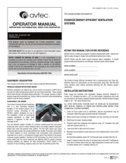
OPERATOR MANUAL
IMPORTANT INFORMATION, KEEP FOR OPERATOR
888-994-7636, fax 888-864-7636
uniedbrands.net
PART NUMBER PP MNL1102, REV. C (08/23)
This manual provides information for:
ECOARCH ENERGY EFFICIENT VENTILATION
SYSTEMS
THIS MANUAL MUST BE RETAINED FOR FUTURE REFERENCE. READ,
UNDERSTAND AND FOLLOW THE INSTRUCTIONS AND WARNINGS CONTAINED
IN THIS MANUAL.
FOR YOUR SAFETY Do not store or use gasoline or other ammable vapors
and liquids in the vicinity of this or any other appliance.
NOTIFY CARRIER OF DAMAGE AT ONCE It is the responsibility of the
consignee to inspect the container upon receipt of same and to determine
the possibility of any damage, including concealed damage. Avtec suggests
that if you are suspicious of damage to make a notation on the delivery
receipt. It will be the responsibility of the consignee to le a claim with the
carrier. We recommend that you do so at once.
Manufacture Service/Questions 888-994-7636.
RETAIN THIS MANUAL FOR FUTURE REFERENCE
NOTICE: Due to a continuous program of product improvement, Avtec reserves the
right to make changes in design and specications without prior notice.
NOTICE: Please read the entire manual carefully before installation. If certain
recommended procedures are not followed, warranty claims will be denied.
MODEL NUMBER _________________________
SERIAL NUMBER _________________________
INSTALLATION DATE ______________________
EQUIPMENT DESCRIPTION
This manual covers three of the basic types of systems offered by Avtec:
MODULAR GREASE EXTRACTORS SERIES
Extractor ventilators are listed by UL and are built in accordance of NFPA-96 for
use with UL listed extinguishing systems for duct hood protection. These models
utilize high velocity removable grease extractors. The canopy contains a hidden
grease trough and removable cup. Surface, plenum and duct collar extinguishing
systems may be factory supplied.
ULTRAVIOLET (UV) SERIES
The EcoArch Energy Efcient Ventilation
UVc is a door assembly integrally
installed in the exhaust plenum of an
EcoArch canopy, consisting of UVc
ltration system designed for use in
the ventilation control of commercial
cooking operations of listed hood
systems. A depiction of this unit is
indicated at left.
The UVc ltration system consists of a Heraus manufactured UVc and Ozone
producing lamp used to reduce exhaust odors and grease deposit emissions
before they enter the exhaust duct system. The UVc light waves and ozone
producing lamp breaks the grease particles into smaller molecules which allow
an Ozone reaction to occur chemically. Like combustion, high temperature
separates the O-atoms in atmospheric Oxygen which then bonds to the grease
molecule causing oxidation. Similarly, in UVc technology, the extra O-atom in the
Ozone splits from the ozone molecule and attaches itself to grease molecule
causing oxidation but without the high temperature, which results in the
reduction of duct cleaning, cleaning costs and risks of potential grease res.
The EcoArch Energy Efcient Ventilation UVc is manufactured with Type 201
Stainless Steel; but, alternatively can be constructed using 200, 300 and 400
series stainless steel without adversely affecting the UVc ltration system
capabilities.
INSTALLATION INSTRUCTIONS
Avtec hoods are provided with adjustable hanging brackets designed to
receive 1/2” threaded rod with a 1/2” nut and washer. Supporting rods must
be connected to all factory supplied/installed brackets. Recommended hanging
height is 78” - 80” above nished oor.
ALL AVTEC VENTILATION SYSTEMS MUST BE INSTALLED IN ACCORDANCE
WITH NFPA-96, REMOVAL OF SMOKE AND GREASE-LADEN VAPORS FROM
COMMERCIAL COOKING EQUIPMENT.
1. Check all local codes prior to installation. Special requirements may be
necessary depending upon building material construction.
2. Move crated hood to location of installation and very carefully uncrate hood.
3. Raise hood to proper hanging height.
4. Suspend hood from adequate roof supports using 1/2” threaded rods with
nuts and washers (See Fig. 1).
5. Level hood left to right and front to back.
6. Brackets are provided for hoods which are to be installed end to end or back
to back.
Bolt brackets together using 3/8” bolt through holes provided (See Fig. 2).
7. Install C channel where the ends of the hood meet and install T moldings on
front face of hoods where they join. High temperature silicone can be used
to install channel and T moldings (See Fig. 3).
Information contained in this document is known to be current and accurate at the time of printing/creation. Reference our product line website for the most updated product information and
specications. © 2023 Electrolux Professional, Inc. All Rights Reserved.
2 OM-ECOARCH
IMPORTANT - READ FIRST - IMPORTANT
CAUTION: DO NOT ATTEMPT TO SERVICE THIS UNIT YOURSELF AS REMOVING COVERS
MAY CAUSE UNNECESSARY EXPOSURE TO DANGEROUS VOLTAGE.
CAUTION: NEVER CONNECT THE UNIT TO A POWER SOURCE WHILE STANDING IN
WATER. WET HANDS AND WET FLOORS SHOULD BE AVOIDED WHEN
CONNECTING ANY ELECTRICAL APPLIANCE TO A POWER OUTLET.
CAUTION: FANS MAY HAVE MULTIPLE POWER CONNECTIONS. MAKE SURE ALL FANS
ARE ISOLATED FROM POWER PRIOR TO PERFORMING MAINTENANCE.
8. For make-up air hoods, the supply collar with built-in UL listed damper and
air volume damper must be installed per instructions on collar.
9. Provide a removable service door in supply duct near damper (See Fig. 4).
Installation Instructions
INSTALLATION REQUIREMENTS
FOR ALL AVTEC ECOARCH
VENTILATION HOODS
CANOPIES
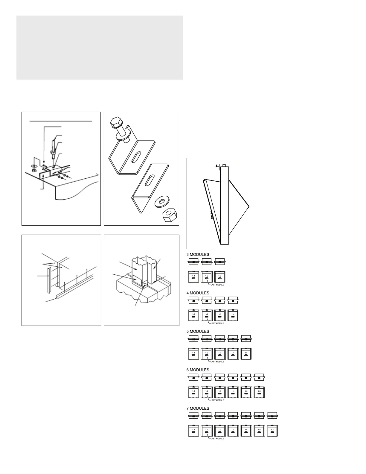
Figure 1 Figure 2
HANGER BRACKET DETAIL
S.S. NUT & BOLT
BY OTHERS
HANGER ROD
HANGER ROD
NUT
Avtec hoods are provided with adjustable hanging brackets designed to receive 1/2”
threaded rod with a 1/2” nut and washer. Supporting rods must be connected to all factory
installed brackets. Recommended hanging height is 6’-6” above finished floor for
canopies. Low side wall ventilators should be installed directly upon a Avtec base or on a
rerated wall. If wall mounted, the bottom of the vent should be 36” above finished floor.
ALL AVTEC VENTILATION SYSTEMS MUST BE INSTALLED IN ACCOR-
DANCE WITH NFPA-96, REMOVAL OF SMOKE AND GREASE-LADEN
VAPORS FROM COMMERCIAL COOKING EQUIPMENT.
1. Check all local codes prior to installation. Special requirements may be necessary
depending upon building material construction.
2. Move crated hood to location of installation and very carefully uncrate hood.
3. Raise hood to proper hanging height.
4. Suspend hood from adequate roof supports using 1/2
" threaded rods with nuts
and washers (See Fig. 1).
5. Level hood left to right and front to back.
6. Brackets are provided for hoods which are to be installed end to end or back to back.
Bolt brackets together using 3/8
" bolt through holes provided (See Fig. 2).
7. Install C channel where the ends of the hood meet and install T moldings on front
face of hoods where they join. High temperature silicone can be used to install
channel and T moldings (See Fig. 3).
8. For make-up air hoods, the supply collar with built-in UL listed damper and
air volume damper must be installed per instructions on collar.
9. Provide a removable service door in supply duct near damper (See Fig. 4).
Figure 3 Figure 4
EXHAUST DUCT
INSULATED
PRE-DRILLED
HOLE, ACCEPTS
UP TO 1/2"ÿ ROD
PRE-DRILLED
HOLE, ACCEPTS
5/16" BOLT
HOOD
ANGLE
OF HOOD
NOTE: HOLES DRILLED THROUGH HOOD ANGLE BY
INSTALLER AFTER BRACKET ATTACHMENT
POINTS HAVE BEEN DETERMINED.
HOOD FACE
T-MOLDING
C-CHANNEL
SUPPLY DUCT
ACCESS
PANEL
FIRE DAMPER &
VOLUME CONTROL
DAMPER
FLUID WELD
Installation Instructions
INSTALLATION REQUIREMENTS
FOR ALL AVTEC ECOARCH
VENTILATION HOODS
CANOPIES
Figure 1 Figure 2
HANGER BRACKET DETAIL
S.S. NUT & BOLT
BY OTHERS
HANGER ROD
HANGER ROD
NUT
Avtec hoods are provided with adjustable hanging brackets designed to receive 1/2”
threaded rod with a 1/2” nut and washer. Supporting rods must be connected to all factory
installed brackets. Recommended hanging height is 6’-6” above finished floor for
canopies. Low side wall ventilators should be installed directly upon a Avtec base or on a
rerated wall. If wall mounted, the bottom of the vent should be 36” above finished floor.
ALL AVTEC VENTILATION SYSTEMS MUST BE INSTALLED IN ACCOR-
DANCE WITH NFPA-96, REMOVAL OF SMOKE AND GREASE-LADEN
VAPORS FROM COMMERCIAL COOKING EQUIPMENT.
1. Check all local codes prior to installation. Special requirements may be necessary
depending upon building material construction.
2. Move crated hood to location of installation and very carefully uncrate hood.
3. Raise hood to proper hanging height.
4. Suspend hood from adequate roof supports using 1/2
" threaded rods with nuts
and washers (See Fig. 1).
5. Level hood left to right and front to back.
6. Brackets are provided for hoods which are to be installed end to end or back to back.
Bolt brackets together using 3/8
" bolt through holes provided (See Fig. 2).
7. Install C channel where the ends of the hood meet and install T moldings on front
face of hoods where they join. High temperature silicone can be used to install
channel and T moldings (See Fig. 3).
8. For make-up air hoods, the supply collar with built-in UL listed damper and
air volume damper must be installed per instructions on collar.
9. Provide a removable service door in supply duct near damper (See Fig. 4).
Figure 3 Figure 4
EXHAUST DUCT
INSULATED
PRE-DRILLED
HOLE, ACCEPTS
UP TO 1/2"ÿ ROD
PRE-DRILLED
HOLE, ACCEPTS
5/16" BOLT
HOOD
ANGLE
OF HOOD
NOTE: HOLES DRILLED THROUGH HOOD ANGLE BY
INSTALLER AFTER BRACKET ATTACHMENT
POINTS HAVE BEEN DETERMINED.
HOOD FACE
T-MOLDING
C-CHANNEL
SUPPLY DUCT
ACCESS
PANEL
FIRE DAMPER &
VOLUME CONTROL
DAMPER
FLUID WELD
FIGURE 1 FIGURE 2
FIGURE 3 FIGURE 4
ECOARCH CANOPIES EQUIPPED WITH UV ASSEMBLY
If your EcoArch hood comes equipped with an UV assembly please refer to the
following steps.
General CAUTIONS & Guidelines:
• Installation of UV Exhaust canopies must be completed by HVAC ventilation
system contractors or employees trained and qualied to do ventilation hood
and exhaust system installation.
• All Fire Suppression System work must be completed by contractors or
employees trained and qualied to do commercial kitchen exhaust hood re
suppression system installation.
• All work must conform to local and national building and NFPA 96 codes and
requirements.
• This document covers installation of the UV mechanical components and
electric connections.
• Electric work must be performed by licensed contractors in accordance with
the current National Electric Code and all national, regional and local codes
that apply.
• Read and review these instructions BEFORE attempting to install this unit.
For best results, follow the installation sequence…as described.
Follow steps 1-7 as outlined for standard EcoArch canopy installation under
Installation Instructions previously provided.
8. Install grease extractors as shown in (Fig. 5). Be certain the extractors are
seated properly as the UVc bulb will not operate without safety contacts
being engaged.
9. Open door on face of canopy by twisting the supplied locking handle in order
to install UVc bulb per supplied diagram. Be certain to close door tightly and
engage handle latch in order to engage safety contacts. UVc bulb will not
operate without safety contacts engaged.
10. Check to see that pressure switch tubing is installed on the low port of
switch and the port on top of the hood located in the s/s enclosure.
11. Install power to UV system as described in Electrical section. See wiring
diagram at end of this document.
Modules (Figure 5)
Product specificaties
| Merk: | Avtec |
| Categorie: | Afzuigkap |
| Model: | EA2 |
Heb je hulp nodig?
Als je hulp nodig hebt met Avtec EA2 stel dan hieronder een vraag en andere gebruikers zullen je antwoorden
Handleiding Afzuigkap Avtec
1 September 2025

1 September 2025
Handleiding Afzuigkap
- Maytag
- Tesy
- Bielmeier
- Trade-Wind
- Fotile
- Apelson
- Dominox
- Emilia
- Cylinda
- Tecnolux
- Hiberg
- Wolkenstein
- Scholtes
- Dacor
- Zanker
Nieuwste handleidingen voor Afzuigkap

2 September 2025
2 September 2025
2 September 2025

2 September 2025

2 September 2025
2 September 2025
2 September 2025
2 September 2025
2 September 2025
2 September 2025