Aube TH132 A Handleiding
Aube
Thermostaat
TH132 A
Bekijk gratis de handleiding van Aube TH132 A (3 pagina’s), behorend tot de categorie Thermostaat. Deze gids werd als nuttig beoordeeld door 217 mensen en kreeg gemiddeld 4.4 sterren uit 109 reviews. Heb je een vraag over Aube TH132 A of wil je andere gebruikers van dit product iets vragen? Stel een vraag
Pagina 1/3

n
o
p
q
r
s
t
u/
v
w
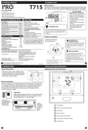
Control Module
TH132 A/F/AF
Owner’s Guide
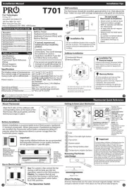
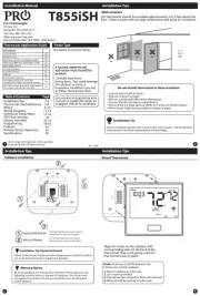
TH132 Description
Models Overview
Configure the Switches
n
o
n
o
n
n
o
Install the Control Module
First Power ON
Set the Time and Day
Adjust the Temperature Setpoints
Select the Operating Mode

n
o
p
q
r
s
n
o
p
n
o
p
q
r
s
n
o
p
q
r
s
t
u
v
Program Your Schedule
Temperature Control Technical Specifications
Warranty

PB130 400-130-001-E 19/9/05 1/1
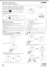
nOne (1) PB130-230 power base
oOne (1) floor sensor (for AF and F control modules only)
pOne (1) wall plate (optional, in certain countries)
Turn off power to the heating system at the main power panel to avoid
electrical shock. Installation should be carried out by an electrician.
All work must conform to the applicable country standards for
electrical installations and wiring.
This thermostat should be connected on a circuit equipped with
a fuse or a circuit breaker. It must be installed on a certified
electrical box.
For a new installation, choose a location about 1.5 m above the
floor.
For electric baseboards, convectors and fan-forced heaters, the
thermostat must be installed facing the heating system.
The thermostat must be installed on an inside wall.
Avoid locations where there are air drafts (top of staircase, air
outlet), dead air spots (behind a door), direct sunlight or
concealed chimneys or stove pipes.
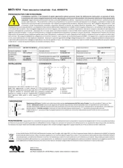
Model: PB130A-230
Supply: 230 VAC, 50 Hz
Load: 15 A maximum (resistive only)
Power: 3450 Watts (NI) @ 230 VAC
Conformity: EN60730-2-9 / EN50081-1 / EN50082-2
Storage: -20°C to 50°C
Protection: Class 2
Protection degree: IP21
Automatic action: Type 1.B
Environment: Normally polluted
Size (H • W • D) : 2.95 x 2.95 x 0.55 in. (75 x 75 x 14 mm)
NOTE: The terminals are designed to handle a cross-section of wire
measuring 0.33 to 3.1 mm2.
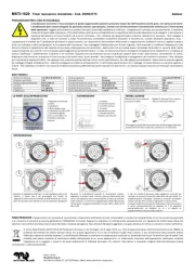
nRemove the screw holding the
control module to the power base
and lift the lower part upwards.
The screw cannot be completely
removed.
pConnect the wires:
• :Power
Terminals 1 & 5
• Load:
Terminals 2 & 4
see note 1
• Pilot Wire:
Terminal 3
see note 2
• :Floor sensor
Terminals 6 & 7
(no polarity)
see note 3
Note 1 If a contactor is used between the thermostat and the load,
install a snubber at the contactor’s coil terminal to ensure
the proper operation of the thermostat.
Note 2 This connection is required on some models only.
Note 3 For the proper operation of the thermostat, the floor sensor
must be centered between two heater wires having a
maximum temperature of 80°C. The floor sensor wire must
not cross any heater wire or be placed close to it.
rPush wires into the electrical box and
secure the base to the electrical box
anchorage. The head of the screw
must be less than 2 mm thick.
sBEFORE installing the control
module onto the base, set the
configuration switches (if any)
on the control module (refer to
the user guide).
WARNING: This power base must be used only with 15-minute
heating cycles. If your control module has a selector switch for
choosing the heating cycle, ensure that the switch is correctly set.
tReturn power to the heating system.
n
n
n
nn
o
o
o
oo 2.
p
p
p
pp 3.
q
q
q
qq 4.
Product specificaties
| Merk: | Aube |
| Categorie: | Thermostaat |
| Model: | TH132 A |
Heb je hulp nodig?
Als je hulp nodig hebt met Aube TH132 A stel dan hieronder een vraag en andere gebruikers zullen je antwoorden
Handleiding Thermostaat Aube

19 Maart 2023

23 Januari 2023

22 Oktober 2022

17 Oktober 2022

9 Oktober 2022
Handleiding Thermostaat
- Daikin
- Elro
- ELV
- Wallair
- Danfoss
- Ambiano
- Maginon
- Gewiss
- Viessmann
- Elektrobock
- Brink
- Cepra
- EBERLE
- Itho
- Nest
Nieuwste handleidingen voor Thermostaat
2 September 2025
1 September 2025
30 Augustus 2025

30 Augustus 2025
26 Augustus 2025
26 Augustus 2025
26 Augustus 2025
26 Augustus 2025
26 Augustus 2025
26 Augustus 2025