Aube TH115 AF Handleiding
Aube
Thermostaat
TH115 AF
Bekijk gratis de handleiding van Aube TH115 AF (3 pagina’s), behorend tot de categorie Thermostaat. Deze gids werd als nuttig beoordeeld door 60 mensen en kreeg gemiddeld 4.9 sterren uit 30.5 reviews. Heb je een vraag over Aube TH115 AF of wil je andere gebruikers van dit product iets vragen? Stel een vraag
Pagina 1/3

TH115 A/F/AF 400-115-003-B 27/2/07 1/2
Aube’s TH115 programmable thermostats have three temperature
control modes:
1 Place the switch in Standby to cut power to the heater when not in use (e.g., in the sum-
mer). This will not affect the time and temperature settings.
2 If your thermostat is installed on a power base equipped with a ground fault protection,
to reset the ground fault protection, switch the thermostat to Standby and back to On.
3 The thermostat displays the percentage of heating time required to maintain the desired
temperature. For example, is displayed when heating is activated 40 percent of the
time.
4 GFI appears when the ground fault protection has tripped.
Some thermostat configurations can be modified via
switches on the back of the faceplate (control module).
Default (factory) settings are inside the gray cells.
nRefer to the installation
instructions of the power
base.
oInsert the tabs at the top of
the control module in the slots
at the top of the power base.
pSecure the control module
using the captive screw
underneath the base.
NOTE
: Keep the thermostat's air vents clean and unobstructed at all times.
nPress the Hour button to set the hour.
oSet the Min button to set the minutes.
pSet the Day button to set the day.
qPress Mode/Ret to exit.
The thermostat can automatically re-adjust its clock at Daylight Sav-
ings Time changeover. When this function is enabled (On), the ther-
mostat switches to Daylight Savings Time on the second Sunday of
March and to normal time on the first Sunday of November.
NOTE: The function is disabled (default setting) when the clock loses
its setting.
nPress the Day DLS button (3 seconds) until appears
on the screen.
oPress the to toggle between On (enabled) and Off
(disabled).
pPress the Day button briefly. The year setting is dis-
played.
qPress the to set the current year.
rPress the Day button briefly. The month setting is dis-
played.
sPress the to set the current month.
tPress the Day button briefly. The date setting is dis-
played.
uPress the to set the current date.
vPress Mode/Ret to exit.
The display illuminates for 12 seconds when the backlight button is
pressed.
When either of the buttons is pressed, the display also illuminates
for 12 seconds. The setpoint temperature appears for 5 seconds,
then the actual (measured) temperature is displayed.
The thermostat normally displays the actual (measured) temperature.
To view the setpoint, press one of the buttons once. The setpoint
will appear for the next 5 seconds.
To change the setpoint, press one of the buttons until the desired
temperature is displayed. To scroll faster, press and hold the button.
The thermostat has 3 preset temperatures:
Comfort temperature
Economy temperature
Vacation temperature
To use a preset temperature, press the corresponding button. The
corresponding icon , or will be displayed.
The following table shows the intended use and the default setting of
each of the preset temperatures.
To store a preset temperature:
nSet the desired temperature using the buttons.
oPress and hold the corresponding button until the corresponding
icon is displayed.
n
n
n
nn 1.
A mode: controls the ambient air temperature
F mode: controls the floor temperature using an
external temperature sensor
AF mode: controls the ambient air temperature
maintains the floor temperature within desired
limits using an external temperature sensor
Display
% of heating time 1 to 24% 25 to 49% 50 to 74% 75 to 99% 100%
o
o
o
oo 2.
# Configurations UP DN
1 Display format °F / 12 h °C / 24 h
2Early Start a
a. Early Start can be used in Automatic mode only. When this function is enabled, the
thermostat calculates the optimal time to start heating in order to obtain the desired
temperature by the set time. The thermostat re-assesses the start time daily based
on the previous day’s results.
Enable Disable
3Temperature control mode b
b. To select the F mode, place the switch in the F position. To select the AF mode,
place the switch in the AF position and ensure that the remote temperature sensor
is connected to the thermostat. To select the A mode, place the switch in the AF
position and ensure that the remote temperature sensor is NOT connected to the
thermostat.
F AF
p
p
p
pp 3.
On/Standby switch 1
and GFCI reset 2
Day and time
settings
Temperature
adjustment buttons
Program button
Mode selection /
program exit
Temperature display
Mode display
Period display
Temperature
preset buttons
Time and day display
Percentage of
heating time 3
Backlight button
Program
clear button
Preset temperature
indicator
Appears when the
setpoint is displayed
Temperature control
mode indicator
Ground fault indicator 4
Power base
Control module
Air vents
Air vents
q
q
q
qq 4.
r
r
r
rr 5.
s
s
s
ss 6.
Icon Intended use A/AF modes F mode
Comfort
(when at home) 21 °C (70 °F) 28 °C (82 °F)
Economy
(when asleep or away from home) 17 °C (63 °F) 20 °C (68 °F)
Vacation
(during prolonged absence) 10 °C (50 °F) 10 °C (50 °F)

TH115 A/F/AF 400-115-003-B 27/2/07 2/2
NOTE: To avoid damaging your floor, follow your floor supplier’s recom-
mendations regarding floor temperature limits.
The minimum and maximum floor temperature limits are 5 °C (41 °F) and
28 °C (82 °F) by default. To modify these limits, proceed as follows:
nSwitch the thermostat to Standby.
oPress and hold the button.
pSwitch the thermostat back to On.
qRelease the button when the minimum temperature
limit ( ) appears.
rSet the minimum temperature limit using the buttons.
sPress the button to display the maximum temperature
limit ( ).
tSet the maximum temperature limit using the buttons.
uPress Mode/Ret to exit.
The thermostat has 3 modes of operation.
The thermostat follows the programmed schedule. To place the ther-
mostat in this mode, press Mode/Ret until is displayed. The data of
the current schedule period are also displayed.
If you modify the setpoint temperature (by pressing the , or
button) when the thermostat is in automatic mode, the new tempera-
ture will be used until the beginning of the next period. flashes dur-
ing the bypass. You can cancel the bypass by pressing Mode/Ret.
The schedule consists of 4 periods per day which represents a typi-
cal week day. You can program the thermostat to skip the periods
that do not apply to your situation. For example, you can skip periods
2 and 3 for the weekend.
The Comfort ( ) temperature is used in periods 1 and 3 and the
Economy ( ) temperature is used in periods 2 and 4. For example,
when the period changes from 1 to 2, the setpoint automatically
changes from Comfort ( ) temperature to Economy ( ) temperature.
You can have a different program for each day of the week; i.e., each
period can start at different time for each day of the week. The
thermostat has been programmed with the following schedule.
To modify the schedule:
nPress Pgm to access the programming mode. Period 1 is
selected.
oPress Day to select the day to program (hold for 3 seconds to
select the entire week).
pPress Hour and Min to set the start time of the selected period,
or press Clear if you want to skip the period (--:-- is displayed).
NOTE: If you intend to use only 2 periods, set periods “1 and 4”
or periods “2 and 3”. Early Start will not work if you set periods
“1 and 2” or periods “3 and 4” .
qPress Pgm to select another period, or press Day to select
another day. Then repeat step 3.
rPress Mode/Ret to exit the programming mode.
NOTE: If no button is pressed for 60 seconds, the thermostat will
automatically exit the programming mode.
The programmed schedule is not used. The temperature must be set
manually. To place the thermostat in this mode:
nPress Mode/Ret until is displayed.
oSet the temperature using the , or button.
In this mode, the thermostat is set to Vacation temperature. There
are two ways to place the thermostat in Vacation mode:
By pressing the button on the thermostat. When the Vacation
mode is activated using the button, the icon appears on the
screen without flashing.
From an Aube telephone controller (CT240/CT241) or any other
remote control device equipped with a dry contact if your power
base is equipped with the ECONO input. When the contact
closes, the Vacation mode is activated and the icon flashes on
the screen. All buttons on the thermostat are locked. When the
contact opens, the thermostat returns to the preceding mode.
NOTE: When the Vacation mode is activated using a remote
control device, it can only be deactivated using the device.
The measured temperature is below the thermostat’s display
range. Heating is activated.
The measured temperature is above the thermostat’s display
range. Heating is deactivated.
Verify the thermostat and sensor connections.
:
Power supply: Refer to the power base’s installation guide.
Display range: 0 °C to 70 °C (32 °F to 158 °F)
Ambient setpoint range (A/AF modes)
: 5 °C to 30 °C (40 °F - 86 °F)
Floor setpoint range (F mode): 5 °C to 40 °C (40 °F - 104 °F)
Floor limit range (AF mode): 5 °C to 40 °C (40 °F - 104 °F)
Display resolution: 0.5 °C (1 °F)
Operating temperature: 0 °C to 50 °C (32 °F to 120 °F)
Storage temperature: -20 °C to 50 °C (-4 °F to 120 °F)
Heating cycle length: Refer to the power base’s installation guide
Data backup: In the event of a power failure, most settings are saved.
Only the time must be re-adjusted if the power failure lasts more than 6
hours. The thermostat will return to the mode that was active prior to the
power failure.
Aube warrants this product, excluding battery, to be free from defects in the work-
manship or materials, under normal use and service, for a period of three (3) years
from the date of purchase by the consumer. If at any time during the warranty
period the product is determined to be defective or malfunctions, Aube shall repair
or replace it (at Aube's option).
If the product is defective,
(i) return it, with a bill of sale or other dated proof of purchase, to the place from
which you purchased it, or
(ii) contact Aube. Aube will make the determination whether the product should
be returned, or whether a replacement product can be sent to you.
This warranty does not cover removal or reinstallation costs. This warranty shall
not apply if it is shown by Aube that the defect or malfunction was caused by dam-
age which occurred while the product was in the possession of a consumer.
Aube's sole responsibility shall be to repair or replace the product within the terms
stated above. AUBE SHALL NOT BE LIABLE FOR ANY LOSS OR DAMAGE OF
ANY KIND, INCLUDING ANY INCIDENTAL OR CONSEQUENTIAL DAMAGES
RESULTING, DIRECTLY OR INDIRECTLY, FROM ANY BREACH OF ANY WAR-
RANTY, EXPRESS OR IMPLIED, OR ANY OTHER FAILURE OF THIS PROD-
UCT. Some provinces, states or regions do not allow the exclusion or limitation of
incidental or consequential damages, so this limitation may not apply to you.
THIS WARRANTY IS THE ONLY EXPRESS WARRANTY AUBE MAKES ON THIS
PRODUCT. THE DURATION OF ANY IMPLIED WARRANTIES, INCLUDING THE
WARRANTIES OF MERCHANTABILITY AND FITNESS FOR A PARTICULAR
PURPOSE, IS HEREBY LIMITED TO THE THREE-YEAR DURATION OF THIS
WARRANTY. Some provinces, states or regions do not allow limitations on how
long an implied warranty lasts, so the above limitation may not apply to you.
This warranty gives you specific legal rights, and you may have other rights which
vary from province, state or region to another.
For any questions regarding product installation or operation, contact us
at:
705 Montrichard
Saint-Jean-sur-Richelieu, Quebec
J2X 5K8
Canada
Tel.: (450) 358-4600
Toll-free: 1-800-831-AUBE
Fax: (450) 358-4650
E-mail: aube.service@honeywell.com
For more information on our products, visit us at:
www.aubetech.com
t
t
t
tt 7.
Period Description Associated temperature setting
Wake-up
Away from home
Return home
Sleep
Period Setting MO TU WE TH FR SA SU
6:00 6:00 6:00 6:00 6:00 6:00 6:00
8:30 8:30 8:30 8:30 8:30 --:-- --:--
17:00 17:00 17:00 17:00 17:00 --:-- --:--
23:00 23:00 23:00 23:00 23:00 23:00 23:00
u
u
u
uu 8.
v
v
v
vv 9.
;10.
11.

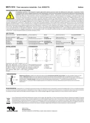
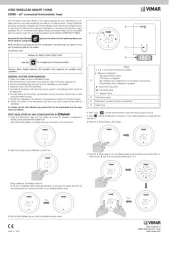
PB112 400-112-006-C 26/2/07 1/1
nOne (1) power base
oTwo (2) screws
pFour (4) solderless connectors for copper wires
NOTE: Special CO/ALR solderless connectors must be used for connecting
aluminum conductors.
Option
qOne (1) AC112-01 floor sensor (ordered separately; required for floor
heating applications only)
Turn off power to the heating system at the main electrical panel to
avoid electrical shock. The installation should be carried out by an elec-
trician.
NOTE: This power base must be used with thermostat operating on
15-minute cycles.
High voltage thermostats must be installed onto an electrical box.
The following guidelines are not necessary for floor heating applica-
tions:
For a new installation, choose a location about 1.5 m (5 ft) above the
floor and on an inside wall.
The thermostat must be installed on an inside wall facing the heating
system.
Avoid locations where there are air drafts (top of staircase, air outlet),
dead air spots (behind a door), direct sunlight or concealed chimneys or
stove pipes.
nConnect the power base wires to the power supply and load using sold-
erless connectors for copper wires (figure 1).
oFor floor heating applications, insert the floor sensor wires through one
of the two holes below the terminals (figure 2) and connect the wires to
terminals 3 and 4 (no polarity).
NOTE: The wires must run alongside the terminals and not go over
them. The wire must not cross any heating wires nor be placed directly
on a heating wire or adjacent to it. For best performance, the sensor
probe should be centered between the wires in the mat.
WARNING: This power base does not have a built-in ground protection
device. Therefore, for floor heating applications, you must install a sepa-
rate ground protection device at the main electrical panel. Contact your
Aube authorized representative if you need a thermostat with built-in
ground protection device.
pIf you wish to use a remote controller such as the CT240 or CT241,
insert the cable (use 18 to 22 gauge flexible wires) into one of the two
holes available below the terminal board and connect to terminals 1 and
2 of the base (figure 2).
qPush the excess length of the high-voltage wires back into the electrical
box.
rSecure the power base to the electrical box using the provided screws.
sIf necessary, set the configuration switches on the control module (refer
to the control module user guide).
tInstall the control module onto the base.
uApply power to heating system.
Storage: -4°F to 120°F (-20°C to 50°C)
Remote controller input (ECONO): requires a dry contact
Size (H • W • D): 4.89 x 2.76 x 0.91 in. (124 x 70 x 23 mm)
Certifications:
n
n
n
nn 1.
o
o
o
oo 2.
p
p
p
pp 3.
q
q
q
qq 4.
Model Supply Max. Load Power Wiring
120S 120 VAC, 50/60Hz 16.7 A 2000 W 4 wires / single pole
240S 240 VAC, 50/60Hz
208 VAC, 50/60Hz 16.7 A 4000 W
3475 W 4 wires / single pole
240D 240 VAC, 50/60Hz
208 VAC, 50/60Hz 15 A 3600 W
3120 W 4 wires / double pole
Power
Load
Figure 1
Figure 2
400-112-006-C (PB112-120-240) ENG.fm Page 1 Monday, February 26, 2007 1:32 PM
Product specificaties
| Merk: | Aube |
| Categorie: | Thermostaat |
| Model: | TH115 AF |
Heb je hulp nodig?
Als je hulp nodig hebt met Aube TH115 AF stel dan hieronder een vraag en andere gebruikers zullen je antwoorden
Handleiding Thermostaat Aube

19 Maart 2023

23 Januari 2023

22 Oktober 2022

17 Oktober 2022

9 Oktober 2022
Handleiding Thermostaat
- TFA
- Optima
- Johnson Control
- Mainstreet Equipment
- ACV
- Helios (Amfra)
- EQ3
- Watts
- Panasonic
- Brink
- ELKO
- Profile
- HomeMatic
- Carel
- Seitron
Nieuwste handleidingen voor Thermostaat
2 September 2025
1 September 2025
30 Augustus 2025
30 Augustus 2025
26 Augustus 2025
26 Augustus 2025
26 Augustus 2025
26 Augustus 2025
26 Augustus 2025
26 Augustus 2025