Apc APBK500EI Handleiding
Bekijk gratis de handleiding van Apc APBK500EI (2 pagina’s), behorend tot de categorie Server. Deze gids werd als nuttig beoordeeld door 61 mensen en kreeg gemiddeld 5.0 sterren uit 31 reviews. Heb je een vraag over Apc APBK500EI of wil je andere gebruikers van dit product iets vragen? Stel een vraag
Pagina 1/2
USB
RJ-45
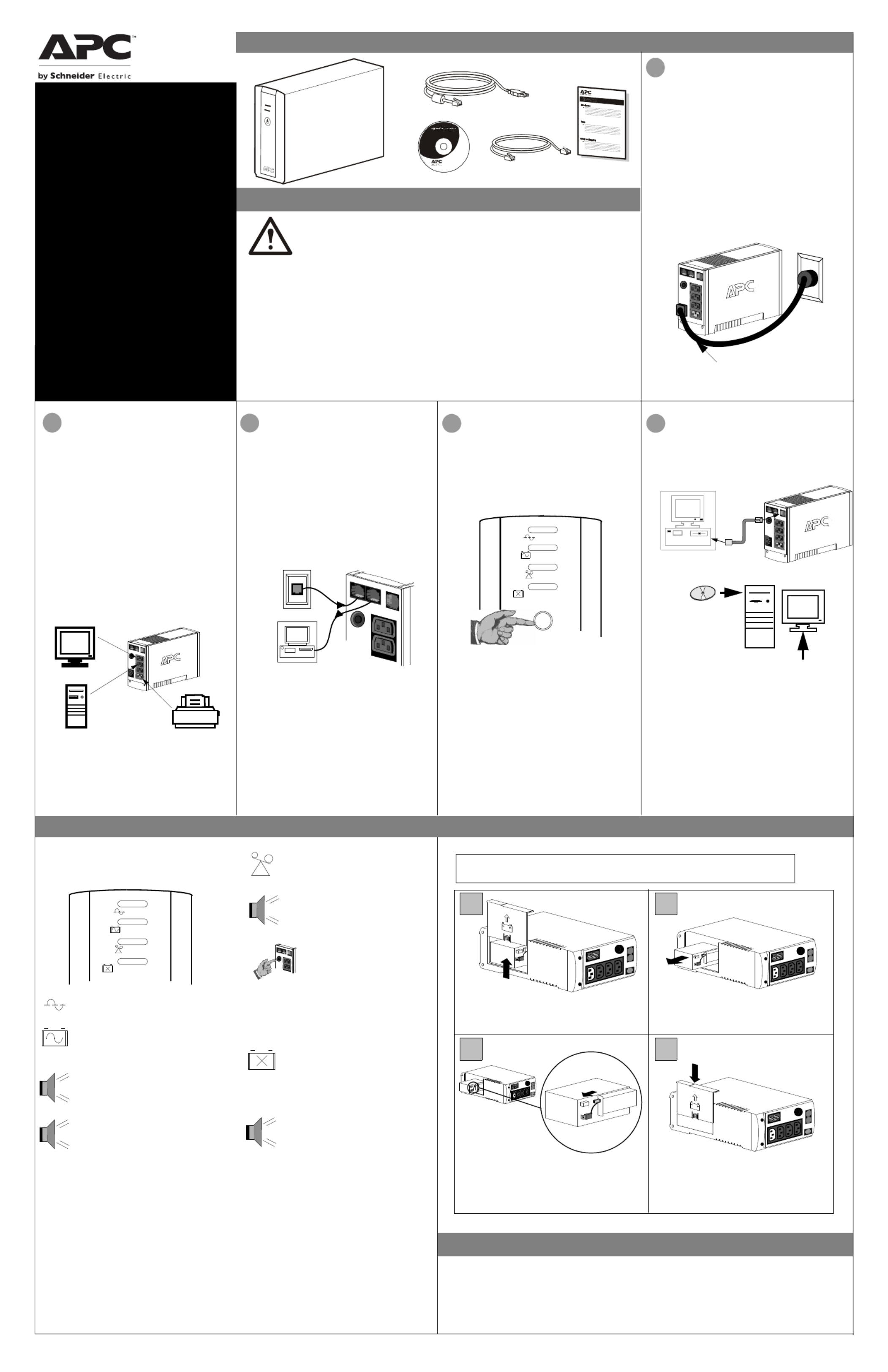
Inventory
2Connect Equipment
Note: Allow the Back-UPS to charge for a full eight
hours prior to use.
Press the push-button on the front panel of the Back-
UPS.
Observe that the following events occur after
pressing and releasing the push-button:
• The green On-Line indicator flashes.
• The yellow On Battery indicator lights while the
Self-Test is being performed.
• When Self-Test has successfully completed, only
the green On Line indicator will be lit.
• If the internal battery is not connected, (see Step
1 above) the green On Line indicator and red
Replace Battery indicator will light. The Back-
UPS will also emit a chirping sound.
ON LINE
ON BATTERY
OVERLOAD
REPLACE BATTERY
5
Connect USB Cable
There are four status indicators (lights) on the front
panel of the Back-UPS (On Line, On Battery,
Overload, and Replace Battery).
On Line (green) - is lit whenever AC
power is powering the Battery Backup
outlets.
On Battery (yellow) - is lit whenever
the battery of the Back-UPS is powering
equipment connected to the Battery
Backup Outlets.
Four Beeps Every 30 Seconds - this
alarm is sounded whenever the Back-UPS
is running On Battery. Consider saving
work in progress.
Continuous Beeping - this alarm is
sounded whenever a low battery condition
is reached. Battery run-time is very low.
Promptly save any work in progress and
exit all open applications. Shutdown the
operating system, computer and the Back-
UPS.
ON LINE
ON BATTERY
OVERLOAD
REPLACE BATTERY
Overload (red) - is lit whenever
power demand has exceeded the capac-
ity of the Back-UPS.
Continuous Tone - this alarm is
sounded whenever the Battery Backup
outlets are overloaded.
Circuit Breaker - the circuit
breaker button located on the rear
panel of the Back-UPS will stick
out if an overload condition forces
the Back-UPS to disconnect itself
from utility power. If the button
sticks out, disconnect non-
essential equipment. Reset the
circuit breaker by pushing the
button inward.
3
Replace Battery (red) - is lit when-
ever the battery is near the end of its use-
ful life, or if the battery is not connected
(see above). A battery that is near the
end of its useful life has insufficient run-
time and should be replaced.
Chirps for 1 Minute Every 5 Hours -
this alarm is sounded whenever the
battery has failed the automatic
diagnostic test.
to the Back-UPS
4
Switch on the
Back-UPS
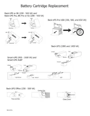
To replace the internal battery, proceed as follows:
Note: Replacing the battery is a safe procedure. However, small sparks may occur
during the process. This is normal.
and Install Software
(optional)
NOTE: Macintosh Users - for full USB
performance, use Mac OS 10.1.5 or higher.
If Autoplay is not enabled on the computer,
proceed as follows:
1. On the computer desktop of the display,
double-click on My Computer.
2. Double-click on the CD-ROM drive icon and
follow the on-screen instructions.
Follow the
on-screen
instructions.
The typical battery lifetime is 3-5 years (depending on the number of discharge cycles and operating
temperature). A replacement battery can be ordered over the phone from Schneider Electric, or the battery
can be ordered on-line from the APC by Schneider Electric web site (http://www.apc.com, a valid credit card
is required).
When ordering, specify Battery Cartridge RBC2 (Back-UPS 350/500) or RBC17 (Back-UPS 650).
Order Replacement Battery
Installation
bu00 1c
1
Placement / Power
• This UPS is intended for indoor use only.
• Do not operate this UPS in direct sunlight, in
contact with fluids, or where there is excessive
dust or humidity.
• Be sure the air vents on the UPS are not blocked.
Allow adequate space for proper ventilation.
• The battery typically lasts for three to five years.
Environmental factors impact battery life.
Elevated ambient temperatures, poor quality AC
power, and frequent short duration discharges will
shorten battery life.
• Connect the UPS power cable directly to a wall
outlet. Do not use surge protectors or extension
cords.
• Plug the Back-UPS into a wall outlet, as shown.
• The Back-UPS charges the internal battery any
time it is connected to a wall outlet.
Your computer’s power cord.
Place the unit on its side. Slide the battery
compartment cover upward and off of the UPS.
21
3 4
Align the battery compartment cover with the
grooves in the UPS. Slide the cover down
until it locks.
Pull the battery out, exposing the battery
terminals and wires. Disconnect the wires from
the terminals.
Slide the new battery into the battery
compartment. Connect the battery wires to the
terminals as follows:
Black wire to Negative (-) terminal
Red wire to Positive (+) terminal
Connect the Phone
Line to Surge
The telephone ports provide lightning surge
protection for any device connected to the telephone
line (computer, modem, fax or telephone). The
telephone ports are compatible with Home Phoneline
Networking Alliance (HPNA) and Digital Subscriber
Line (DSL) standards, as well as all modem data
rates. Connect as shown.
Wall Outlet
Modem/Phone/Fax
Protection
The rear panel of the Back-UPS consists of the
following elements:
Battery Back Up Outlets (qty. of 3). These outlets
provide battery back-up, surge protection, and
Electro-magnetic Interference (EMI) filtering. In
case of power outage, battery power is automatically
provided to these outlets. Power (utility or battery) is
not supplied to these outlets when the Back-UPS is
switched Off. Connect a computer, monitor, and
external disk or CD-ROM drive to these outlets.
Surge Only Outlet. This outlet is always On (when
utility power is available) and is not controlled by
the On/Off switch. This outlet does not provide
power during a power outage. Connect a printer, fax
machine or scanner to this outlet.
Inspect the package contents upon receipt. Notify the carrier and
dealer if there is any damage.
Read the following reminders before installing the UPS.
• This UPS is intended for indoor use only.
• Connect the UPS power cable directly to a wall outlet. Do not use surge protectors or extension cords.
• When grounding cannot be verified, disconnect the equipment from the AC power outlet before installing
or connecting to other equipment. Reconnect the power cord after all connections are made.
• Servicing of batteries should be performed by Schneider Electric IT (SEIT) Customer Support only.
• When replacing battery the UPS must be OFF, and its AC inlet unplugged.
• Do not dispose of batteries in a fire. The batteries may explode.
• Do not open or mutilate batteries. They contain an electrolyte that is toxic and harmful to the skin and
eyes.
• To avoid harmful injury due to energy hazard, remove wrist watches and jewelry such as rings when
replacing the batteries. Use tools with insulated handles.
• Replace batteries with the same number and type of batteries as originally installed in the equipment.
Safety and General Information
EN 990-9237A 10/2014
Back-UPS
™
350/500/650
User Manual
CS
Replace the Internal Battery
Status Indicators and Alarms

Back-UPS does not power computer/monitor/external drive during an outage
Internal battery is not connected.
Computer, monitor or external disk/
CD-ROM drive is plugged into a
Surge Only outlet.
Check the battery connections
Move computer, monitor, or external drive power cord plug to the
Battery Backup outlets.
Back-UPS operates on battery although normal utility voltage exists
Back-UPS circuit breaker “tripped”.
The wall outlet that the Back-UPS is
connected to does not supply utility
power to the unit.
Disconnect non-essential equipment from the
Back-UPS. Reset the circuit breaker (located
on the rear panel of the Back-UPS) by push-
ing the circuit breaker button fully inward
until it catches.
Back-UPS does not provide expected backup time
Back-UPS is excessively loaded.
Back-UPS battery is weak due to
recent outage and has not had time
to recharge.
Battery requires replacement.
Unplug non-essential Battery Backup connected equipment, such as
printers and plug them into Surge Only outlets.
Note: Devices that have motors or dimmer switches (laser printers,
heaters, fans, lamps, and vacuum cleaners, for example) should not be
connected to the Battery Backup outlets.
Charge the battery. The battery charges whenever the Back-UPS is
connected to a wall outlet. Typically, eight hours of charging time are
needed to fully charge the battery from total discharge. Back-UPS
run-time is reduced until the battery is fully charged.
Replace battery (see Order Replacement Battery). Batteries typically
last 3-6 years, shorter if subjected to frequent power outages or
elevated temperatures.
A red indicator is lit
Battery is not connected properly.
The Overload indicator is lit if
equipment connected to the Battery
Backup outlets is drawing more
power than the Back-UPS can pro-
vide.
Battery requires replacement.
Check the battery connections.
Move one or more equipment power plugs to the Surge Only outlets.
The battery should be replaced within two weeks (see “Order
Replacement Battery”). Failure to replace the battery will result in
reduced run-time during a power outage.
Connect the Back-UPS to another wall outlet or have a qualified
electrician check the building wiring.
Red indicators are flashing
Back-UPS failure. Call APC for service.
Service
1. Consult the Troubleshooting section to eliminate common problems.
2. Determine if the circuit breaker is tripped. If the circuit breaker is tripped, reset the breaker and
determine if the problem still exists.
3. If the problem persists, consult the APC Worldwide Web site (www.apcc.com) or call customer
service.
• Record the model number of the UPS, the serial number, and the date purchased. Be prepared to
troubleshoot the problem over the telephone with a technician. If this is not successful, the
technician will issue a Return Merchandise Authorization Number (RMA#) and a shipping
address.
• If the UPS is under warranty, repairs are free. If not, there is a repair charge.
4. Pack the UPS in its original packaging. If the original packing is not available, ask customer service
about obtaining a new set. Pack the UPS properly to avoid damage in transit.
5. Write the RMA# on the outside of the package.
6. Return the UPS by insured, prepaid carrier to the address provided by customer service.
Note: If the UPS requires service, do not return it to the dealer. The following steps should
be taken:
Note: Never use StyrofoamTM beads for packaging. Damage sustained in transit is
not covered under warranty (insuring the package for full value is recommended).
Warranty
The standard warranty is two (2) years from the date of purchase. APC’s standard procedure is to replace
the original unit with a factory reconditioned unit. Customers who must have the original unit back due
to the assignment of asset tags and set depreciation schedules must declare such a need at first contact
with an APC Technical Support representative. APC will ship the replacement unit once the defective
unit has been received by the repair department, or cross ship upon the receipt of a valid credit card num-
ber. The customer pays for shipping the unit to APC. APC pays ground freight transportation costs to
ship the replacement unit to the customer.
Replace Battery indicator lit and an alarm sounds when the Back-UPS is turned on
Internal battery not connected. Check the battery connections.
Transfer Voltage and Sensitivity Adjustment (optional)
Use the tables below to solve minor Back-UPS installation and operation problems. Consult Schneider Elec-
tric IT (SEIT) On-line Technical Support or call SEIT Technical Support for assistance with problems that
cannot be resolved using this document:
Possible Cause Procedure
Back-UPS will not switch on
Back-UPS not connected to an util-
ity power source.
Back-UPS circuit breaker “tripped”.
Very low or no utility voltage.
Portable generator being used to
provide input voltage.
Check that the Back-UPS power plug is
securely connected to the wall outlet.
Disconnect non-essential equipment from the
Back-UPS. Reset the circuit breaker (located
on the rear panel of the Back-UPS) by push-
ing the circuit breaker button fully inward
until it catches. If the circuit breaker resets,
switch the Back-UPS on and reconnect the
equipment one-at-a-time. If the circuit
breaker trips again, it is likely that one of the
connected devices is causing the overload.
Check the wall outlet that supplies power to
the Back-UPS using a table lamp. If the lamp
bulb is very dim, have the utility voltage
checked by a qualified electrician.
Set the Transfer Voltage and Sensitivity
setting to Low (see Transfer Voltage and
Sensitivity Adjustment). By setting the Back-
UPS to Low sensitivity, it can accept a wider
range of input voltage.
Specifications
Input Voltage (on line)
Frequency Limits (on line)
On Battery Waveshape
Maximum Load
Typical Recharge Time
Operating Temperature
Storage Temperature
Operating and Storage
Relative Humidity
Size (H x W x D)
Weight
Shipping Weight
EMI Classification
On Battery Run-Time
Back-UPS Storage
Before storing, charge the Back-UPS for at least eight hours. Store the Back-UPS covered and upright in
a cool, dry location. During storage, recharge the battery in accordance with the following table:
Contact APC Technical Support to troubleshoot the unit before returning it to APC
Storage Temperature Recharge Frequency Charging Duration
-5o to 30oC (23o to 86oF)
30o to 45oC (86o to 113o
F)
Every 6 months
Every 3 months
8 hours
8 hours
180 - 266 Vac (default setting)
47 - 63 Hz (auto-sensing)
Stepped Sine Wave
350 VA - 210 W 500 VA - 300 W 650 VA - 400 W
8 Hours
0o to 40oC (32o to 104oF)
-15o
to 45oC (5o
to 113 oF)
5 to 95% non-condensing
16.5 x 9.2 x 28.5 cm (6.5 x 3.6 x 11.2 inches)
350 VA - 5.7 kg (12.5 lb) 500 VA - 5.9 kg (12.9 lb)
650 VA - 6.2 kg (13.6 lb.)
350 VA - 6.8 kg (14.9 lb) 500 VA - 7.0 kg (15.3 lb)
650 VA - 7.3 kg (16.1 lb.)
EN 55022, IEC 801-2 and 801-4 (level IV), and IEC 801-3 (level III)
350 VA - 13.2 minutes (typical) - computer and
17" (43.2 cm) monitor.
500 VA - 10.8 minutes (typical) - computer and
21" (53.3 cm) monitor.
650 VA - 17 minutes (typical) - computer and
21" (53.3 cm) monitor.
© 2014 APC by Schneider Electric. APC, the APC logo, Back-UPS, and PowerChute are owned by
Schneider Electric Industries S.A.S., or their affiliated companies. All other trademarks
are property of their respective owners.
APC by Schneider Electric IT Customer Support
For country specific customer support, go to the APC by Schneider Electric Web site, www.apc.com.
This equipment has been tested and found to comply with the limits for a Class B digital device, pursuant to
part 15 of the FCC Rules. These limits are designed to provide reasonable protection against harmful inter-
ference in a residential installation. This equipment generates, uses and can radiate radio frequency energy
and, if not installed and used in accordance with the instructions, may cause harmful interference to radio
communications. However, there is no guarantee that a particular installationinterference will not occur in
If this equipment does cause harmful interference to radio or television reception, which can be determined
by turning the equipment off and on, the user is encouraged to try to correct the interference by one or more
of the following measures:
- Reorient or relocate the receiving antenna.
- Increase the separation between the equipment and receiver.
- Connect the equipment into an outlet on a circuit different from that to which the receiver is
connected.
- Consult the dealer or an experienced radio/TV technician for help.
Locate the label on the bottom of this device that contains, among other information, the FCC registration
number [US: 1XH-USA-25572-XP-N]] and ringer equivalence number (REN) for this device. If requested
this information must be provided to the telephone company.
If you experience trouble with this equipment, you disconnect it from the network until the problem has been
corrected or until you are sure that the equipment is not malfunctioning. The ringer equivalence number
(REN) is used to determine how many devices can be connected to your telephone line. In most areas, the
sum of the RENs of all devices on any one line should not exceed five (5.0). If too many devices are
attached, they may not ring properly.
EMI Compliance
Troubleshooting
In situations where the Back-UPS or connected equipment appears too sensitive to input voltage, it may be
necessary to adjust the transfer voltage. This is a simple task requiring use of the front panel pushbutton. To
adjust the transfer voltage, proceed as follows:
1. Plug the Back-UPS into the utility power source. The Back-UPS will be in a Standby Mode (no indicators lit).
2. Press the front panel pushbutton fully inward for 10 seconds. All indicators on the Back-UPS will flash to
acknowledge going into Programming Mode.
3. The Back-UPS will then indicate its current Sensitivity Setting, as shown in the following table.
4. To select the Low Sensitivity setting, press the pushbutton until the yellow indicator is flashing.
5. To select the Medium Sensitivity setting, press the pushbutton until the yellow and red indicators (second and
third from the top) are flashing.
6. To select the High Sensitivity setting, press the pushbutton until yellow and both red indicators (bottom three)
are flashing.
7. To exit without changing the Sensitivity Setting, press the pushbutton until the green indicator is flashing.
8. Once in Programming Mode, if the pushbutton is not pressed within 5 seconds, the Back-UPS will exit
Programming Mode; all indicators will extinguish.
Indicators
Flashing
Sensitivity
Setting
Input Voltage
Range
(for utility
operation)
Use When
1
(yellow)
Low 160 - 278 Vac Input voltage is extremely low or
high. Not recommended for computer
loads.
2
(yellow, and red)
Medium
(factory default)
180 - 266 Vac Back-UPS frequently goes On
Battery.
3
(yellow, red, and red)
High 196 - 256 Vac Connected equipment is sensitive to
voltage fluctuations (recommended).
Product specificaties
| Merk: | Apc |
| Categorie: | Server |
| Model: | APBK500EI |
Heb je hulp nodig?
Als je hulp nodig hebt met Apc APBK500EI stel dan hieronder een vraag en andere gebruikers zullen je antwoorden
Handleiding Server Apc

7 December 2024
2 December 2024

2 December 2024

3 Juni 2023

2 Juni 2023

19 Mei 2023

11 Mei 2023

15 April 2023

8 April 2023

30 Maart 2023
Handleiding Server
- TAIDEN
- Kathrein
- Extron
- Intellinet
- Intel
- Kramer
- Fromm-Starck
- Eaton
- StarTech.com
- HP
- Lantronix
- Allnet
- Advantech
- Asus
- Middle Atlantic
Nieuwste handleidingen voor Server
2 Augustus 2025
1 Augustus 2025

1 Augustus 2025
1 Augustus 2025

1 Augustus 2025

1 Augustus 2025

30 Juli 2025
30 Juli 2025

29 Juli 2025
29 Juli 2025