WyreStorm TX-SW-IW-0201 Handleiding


Lees hieronder de 📖 handleiding in het Nederlandse voor WyreStorm TX-SW-IW-0201 (4 pagina's) in de categorie Niet gecategoriseerd. Deze handleiding was nuttig voor 23 personen en werd door 2 gebruikers gemiddeld met 4.5 sterren beoordeeld

Pagina 1/4
2x1 HDMI/VGA over HDBaseTâ„¢ Auto-Switching 2-Gang
In Wall Transmitter (100m/328ft)
TX-SW-IW-0201 Quickstart Guide
In the Box
1 x TX-SW-IW-0201 HDBaseT Wall Plate Transmitter
1 x 3-pin Plug-in Phoenix Connector
2 x 2pin-plug-in phoenix connectors
1 x Decorative Wall Plate with 4 screws
4 x 6-32x20mm Installation Screws
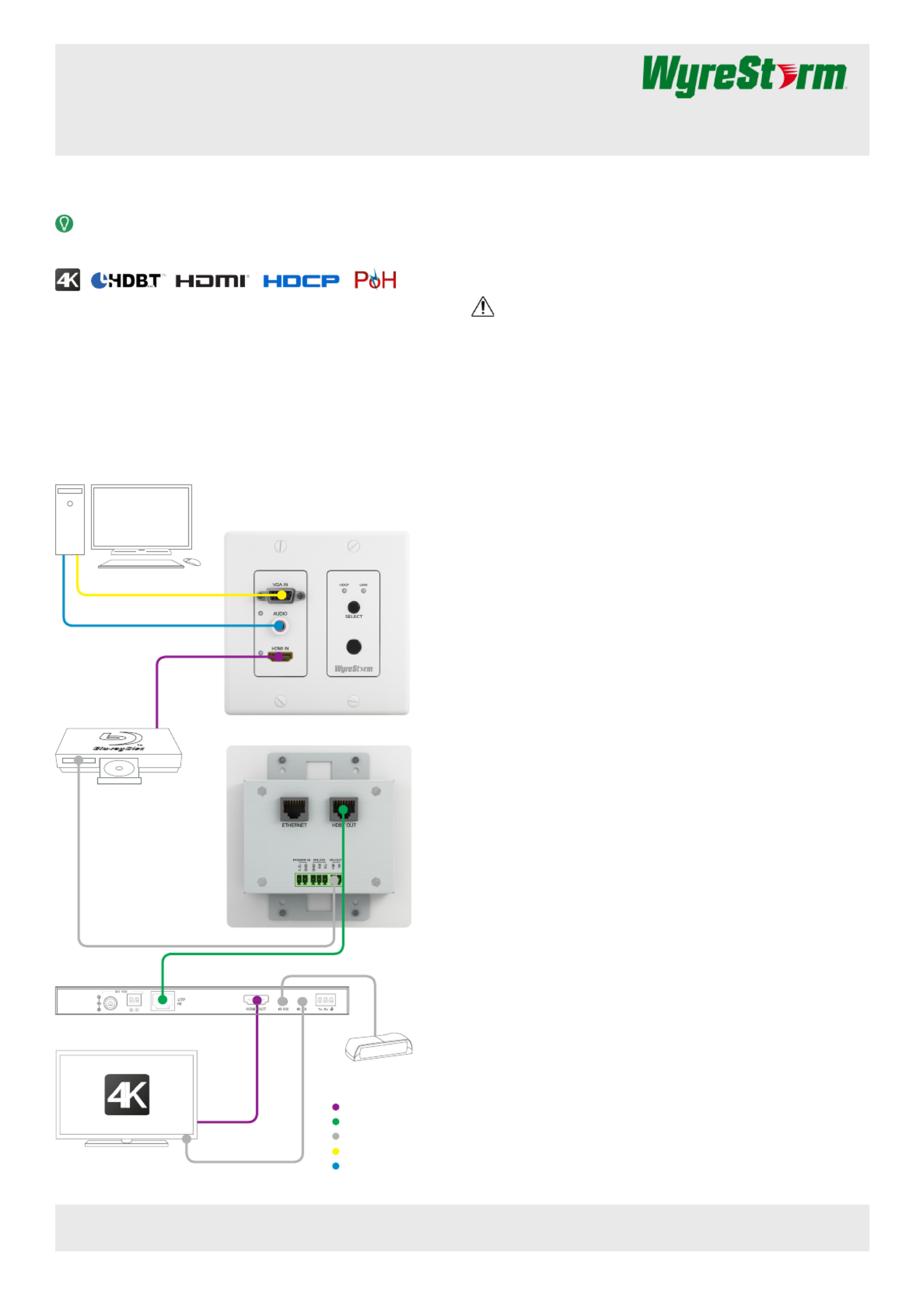
Basic Wiring Diagram
Installation
IMPORTANT! Do not connect or disconnect (hot plug) the HDMI, or
HDBaseT connections while the transmitter is powered on. Doing so may
cause damage to the transmitter or connected devices.
1. Verify that all items are included in the packaging per the list under
the section.In the Box
2. Run a Cat5/5e/6 cable from the transmitter location to the receiver
location. Terminate the cable per the section and HDBaseT Wiring
connect to the on the transmitter.HDBT Out
3. (Optional) Terminate an IR emitter or cable per the section IR Wiring
and connect to the on the transmitter. Place the IR emitter IR Out
onto the source device near the IR receiver or connect to an IR port
on the source.
4. (Optional) Terminate a cable per the section and RS-232 Wiring
connect to the RS-232 pass-through on the transmitter. Connect the
opposite end to a port on a control system.
5. Connect the opposite end of the HDBaseT cable to a WyreStorm
HDBaseT receiver, switcher, or 3rd party display device with built-in
HDBaseT receiver. Power on the receiver.
6. (Optional) If power for the transmitter is not being supplied by the
receiver via PoH, connect a 12V DC 1A power supply (not included)
to the connection on the transmitter. See Power In Power Supply
Wiring.
7. Install the TX-SW-IW-0201 in a dual-gang wall box located near the
source.
8. Connect up to 2 sources to the transmitter.
• Connect a VGA source to the VGA In on the transmitter.
• Connect an HDMI source to the on the transmitter using HDMI In
an HDMI cable from a high quality brand such as WyreStorm
Express.
9. Power on the HDBaseT receiver or connect the power supply to an
AC outlet.
A PoH compatible HDBaseT transmitter with VGA & HDMI inputs, tting into a decora 2-Gang wall box.
Copyright © 2015 WyreStorm Technologies | wyrestorm.com
TX-SW-IW-0201 Quickstart Guide | 150828
North America: 518-289-1294 | EMEA/ROW: 44 (0) 1793 230 343
support@wyrestorm.com
1 of 4
KEY
HDMI
HDBaseT Cat5e/6
IR TX and RX
Analog Video (VGA)
Analog Audio
HDMI from Source
VGA from Source
Audio from Source
IR Out to Source
HDBaseT Cat5e/6
HDMI to
Display
IR TX to Display
IR RX (IR to Transmitter)
TX-SW-IW-0201 Front (with wall-plate)
TX-SW-IW-0201 Rear
HDMI Source
VGA Source
4K HDMI Display
WyreStorm recommends reading through this document in its entirety to become familiar with the product’s features prior to starting the
installation process.
Copyright © 2015 WyreStorm Technologies | wyrestorm.com
TX-SW-IW-0201 Quickstart Guide | 150828
North America: 518-289-1294 | EMEA/ROW: 44 (0) 1793 230 343
support@wyrestorm.com
2 of 4
Front Panel Rear Panel
HDMI IN and HDMI LED
19-pin type A HDMI female digital
video/audio input: Supports HDMI
and DVI/D (requires adapter-not
included). Limited to 297MHz pixel
clock. LED illuminates when HDMI
source is selected.
AUDIO IN
3.5 mm (1/8 in) Stereo Analog
Audio:
Connect to audio output of device
connected to VGA input.
VGA IN and VGA LED
15-pin VGA VESA (D-SUB 15):
Connect to D-SUB 15 VGA output
of a device such as a computer.
LED illuminates when VGA source is
selected.
EDID Settings
3 Position Dipswitch (Under
Faceplate):
Used to set EDID to correct
resolution conicts between the
source and the display.
See EDID Settings.
HDCP LED
Solid: Audio and Video signal is
HDCP protected.
Flashing: Audio and Video signal is
not HDCP protected.
O: No Audio and Video signal.
LINK LED
Solid: Link to receiver has been
established.
Flashing: Link to receiver has not
been established.
SELECT Press to switch between the VGA
and HDMI source inputs.
IR Sensor
30-55kHz IR Receiver.
Receives an IR signal from hand-
held remote or asher that is
transmitted to the remote display via
HDBaseT.
E
POWER IN
2-pin Screw Down Phoenix
Connector
(Optional) Connect to a 12V DC 1A
power supply (not included). Do not
use when powering transmitter via
PoH. See .Power Supply Wiring
ETHERNET
8-pin RJ-45 female
Connect to a router or switch to
supply Ethernet to remote location.
RS-232
3-pin Screw Down Phoenix
Connector
Used to send RS-232 signals to
the remote display location via
HDBaseT.
See RS-232 Wiring.
HDBT OUT
8-pin RJ-45 female
Connect to an HDBaseT receiver.
See for wiring HDBaseT Wiring
details.
IR OUT
2-pin Screw Down Phoenix
Connector
Used to send IR signals sent from
the remote display location via
HDBaseT to a device (source)
located near the transmitter.
See .IR Wiring
E
Copyright © 2015 WyreStorm Technologies | wyrestorm.com
TX-SW-IW-0201 Quickstart Guide | 150828
North America: 518-289-1294 | EMEA/ROW: 44 (0) 1793 230 343
support@wyrestorm.com
3 of 4
Wiring and Connections
HDBaseT Wiring
Wiring for HDBaseT follows the EIA T568B standard.
IMPORTANT! Wiring Guidelines
• The use of patch panels, wall plates, cable extenders, kinks in cables,
and electrical or environmental interference can have an adverse eî‘œect
on HDBaseT transmission limiting performance. Steps should be taken
to minimize these factors (or remove completely) during installation for
best results.
• While similar in nature, the HDBaseT protocol is dierent than Ethernet
and voltages provided for PoH can be higher than those provided by
PoE. For this reason, never connect an HDBaseT link to an Ethernet
router or switch to avoid damaging the connected devices.
Supported Video Resolutions
The type of category cable used and the distance between the transmitter
and receiver can restrict the available video resolution.
Cable Type Range Supported Resolution
Cat5/5e/6
100m/328ft 1080p @ 60Hz 36bit
70m/230ft 3840 x 2160 @ 30Hz 4:4:4
Cat6a 100m/328ft
1080p @ 60Hz 36bit
1080p @ 60Hz 48bit
1080p @ 60Hz 3D
3840 x 2160 @ 30Hz 4:4:4
Note: When connected to a class B HDBaseT receiver, the
supported resolution is limited to 70m/230ft 1080p.
IR Wiring
Connection for an IR emitter or cable to control the local source use a
2-pin Screw Down Phoenix connector.
RS-232 Wiring
Connection for RS-232 pass-through to the display at the remote
location uses a 3-pin Screw Down Phoenix connector. The connector
type and pinout on the control system may vary, refer to the 3rd party
manufacturer’s instructions for details.
Power Supply Wiring
Power for the TX-IW-70-POH is supplied via PoH when connected to a
compatible HDBaseT receiver
When PoH is not available from the connected receiver, connect a 12V
DC 1A power supply (not included) using a 2-pin Screw Down Phoenix
Connector.
EDID Settings
EDID can be congured to resolve issues with video output on displays
that may not accept the maximum resolution available from the source.
Remove the faceplate from the TX-SW-IW-0201 and set the switches
based on the table below.
Pin 1
Pin 8
RJ-45 Connector (Gold Pins Facing Up)
Pin 2: Orange GreenPin 6:
Pin 1: White/Orange Pin 5: White/Blue
Pin 3: White/Green Pin 7: White/Brown
Pin 4: Blue Pin 8: Brown
1920x1080 (default) 1280x720
1280x800 1024x768
1920x1200 800x600


Product specificaties

Merk: WyreStorm
Categorie: Niet gecategoriseerd
Model: TX-SW-IW-0201
Kleur van het product: Zwart
Gewicht: 190 g
Breedte: 108 mm
Diepte: 106.7 mm
Hoogte: 25 mm

Heb je hulp nodig?

Als je hulp nodig hebt met WyreStorm TX-SW-IW-0201 stel dan hieronder een vraag en andere gebruikers zullen je antwoorden


Handleiding Niet gecategoriseerd WyreStorm

Handleiding Niet gecategoriseerd

Nieuwste handleidingen voor Niet gecategoriseerd